Engines Iveco N45, N67. Manual — part 30

70326
18625
18882
70327
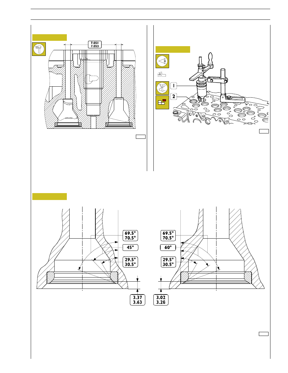
Figure 75
Figure 76
Figure 77
Figure 78
VALVES
INTAKE AND EXHAUST VALVE MAIN DATA
Remove carbon deposits from valves using the proper metal
brush.
Check that the valves show no signs of seizing, scoring or
cracking.
Regrind the valve seats, if required, using tool 99305018 and
removing as less material as possible.
Check the valve stem (1) using a micrometer (2), it shall be
6.970
÷ 6.999.
Use a magnetic base dial gauge (1) set as shown in the figure,
the assembling clearance shall be 0.052
÷ 0.092 mm.
Turn the valve (2) and check that the centering error is not
exceeding 0.03 mm.
Removing carbon deposits, checking and
grinding valves
Checking clearance between valve stem and
valve guide and valve centering
INTAKE
VALVE
EXHAUST
VALVE
34
SECTION 4 - OVERHAUL AND TECHNICAL SPECIFICATIONS
F4HE NEF ENGINES
Base - February 2006
Print P2D32N00GB
EXHAUST
70328
70330
70331
Figure 79
Figure 80
Use a bore dial gauge to measure the inside diameter of the
valve guides, the read value shall comply with the value
shown in the figure.
Check the valve seats (2). If slight scoring or burnout is found,
regrind seats using tool 99305018 (1) according to the angle
values shown in Figure 81.
VALVE SEATS
Regrinding — replacing the valve seats
VALVE SEAT MAIN DATA (4 CYL.)
INTAKE
EXHAUST
INTAKE
Figure 81
VALVE GUIDE
SECTION 4 - OVERHAUL AND TECHNICAL SPECIFICATIONS
35
F4HE NEF ENGINES
Print P2D32N003GB
Base - February 2006

70332
Figure 82
Should valve seats be not reset just by regrinding, replace
them with the spare ones. Use tool 99305018 (Figure 80) to
remove as much material as possible from the valve seats
(take care not to damage the cylinder head) until they can
be extracted from the cylinder head using a punch.
Heat the cylinder head to 80
° - 100°C and using the proper
punch, fit the new valve seats, previously cooled, into the
cylinder head.
Use tool 99305018 to regrind the valve seats according to
the values shown in Figure 81.
MAIN DATA CONCERNING THE SEATS ON THE CYLINDER HEAD (4 CYL.)
EXHAUST
INTAKE
Figure 83
MAIN DATA ABOUT ENGINE VALVE SEATS
Valve seats are installed by cooling onto the cylinder head
and machining to the correct dimension.
CYLINDER HEAD VALVE SEATS (6 CYL.)
70515
EXHAUST
INTAKE
36
SECTION 4 - OVERHAUL AND TECHNICAL SPECIFICATIONS
F4HE NEF ENGINES
Base - February 2006
Print P2D32N00GB

70332
70331
Figure 84
Figure 85
If valve seats cannot be restored just by regrinding, it is
possible to assemble the spare inserts provided.
In this case, it is necessary to install seats into the cylinder
head sized as shown in the figure and to assemble the valve
seats.
VALVE SEAT MAIN DATA (6 CYL.)
In order to assemble the valve seats into the cylinder head,
it is necessary to heat the cylinder head to 80 to 100
°C and,
through a suitable punch, to assemble the new, previously
cooled valve seats (2) into the head.
Then, with tool 99305018, adjust valve seats according to the
values shown in Figure 85.
EXHAUST
INTAKE
EXHAUST
INTAKE
SECTION 4 - OVERHAUL AND TECHNICAL SPECIFICATIONS
37
F4HE NEF ENGINES
Print P2D32N003GB
Base - February 2006
Нет комментариевНе стесняйтесь поделиться с нами вашим ценным мнением.
Текст