Engine Iveco C10/C13/C78/Cursor 13/Cursor 78. Manual — part 11
SECTION 3 - INDUSTRIAL APPLICATION
19
Apply the tool 99360321 (6) to the gearbox (3).
45261
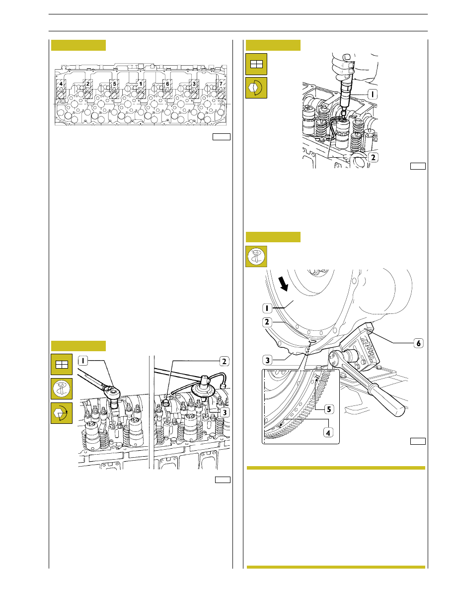
Lock the screws (2) fixing the rocker-arm shaft as follows:
- 1
st
phase: tightening to a torque of 80 Nm (8 kgm) with
the torque wrench (1);
- 2
nd
phase: closing with an angle of 60
° using the tool
99395216 (3).
Mount the electric wiring (2), securing it on the
electro-injectors with a torque screwdriver (1) to a torque
of 1.36 - 1.92 Nm.
α
The arrow shows the direction of rotation of the
engine when running.
Using the above-mentioned tool, turn the engine
flywheel (1) in the direction of rotation of the
engine so as to take the piston of cylinder no.1 to
approximately the T.D.C. in the phase of
combustion.
This condition occurs when the hole with one
reference mark (4), after the hole with two
reference marks (5) on the engine flywheel (1), can
be seen through the inspection window (2).
Figure 55
Figure 56
Figure 57
Camshaft timing
71776
71777
SCHEME OF SCREW TIGHTENING SEQUENCE
SECURING ROCKER ARMS
Screw screws (1 - 2 - 3) until rocker arms are brought to
contact relating seats on cylinder head, tighten the screws
according to sequence indicated in figure operating in two
steps as indicated in successive figure.
70567A
NOTE
Figure 58
20
SECTION 3 - INDUSTRIAL APPLICATION
71774
60575
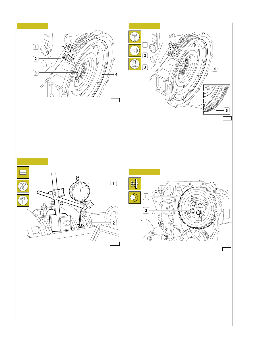
The exact position of piston no.1 at the T.D.C. is obtained
when in the above-described conditions the tool 99360612
(1) goes through the seat (2) of the engine speed sensor into
the hole (3) in the engine flywheel (4).
If this is not the case, turn and adjust the engine flywheel (4)
appropriately.
Remove the tool 99360612 (1).
Set the dial gauge with the magnetic base (1) with the rod
on the roller (2) of the rocker arm that governs the injector
of cylinder no.1 and pre-load it by 6 mm.
With tool 99360321 (6, NO TAG), turn the crankshaft
clockwise until the pointer of the dial gauge reaches the
minimum value beyond which it can no longer fall.
Reset the dial gauge.
Turn the engine flywheel anticlockwise until the dial gauge gives
a reading for the lift of the cam of the camshaft of 4.90
±0.05
mm.
The camshaft is in step if at the cam lift values of 4.90
±0.05 mm
there are the following conditions:
1) the hole marked with a notch (5) can be seen through
the inspection window;
2) thetool 99360612 (1) through theseat (2) of the engine
speed sensor goes into the hole (3) in the engine
flywheel (4).
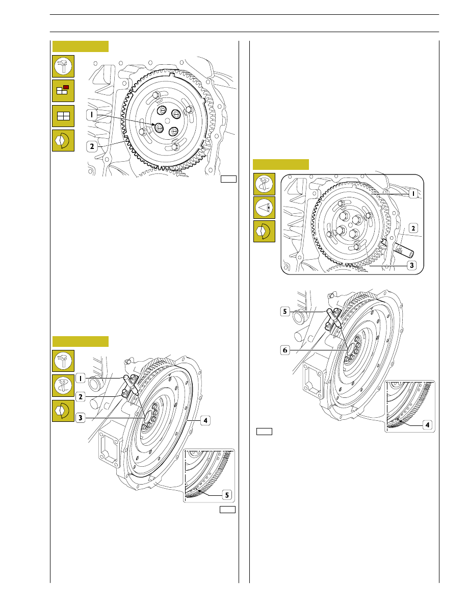
If you do not obtain the conditions illustrated in Figure 61 and
described in points 1 and 2, proceed as follows:
1) loosen the screws (2) securing the gear (1) to the
camshaft and utilize the slots (1, Figure 63) on the gear
(2, Figure 63);
2) turn the engine flywheel appropriately so as to bring
about the conditions described in points 1 and 2
Figure 61, it being understood that the cam lift must not
change at all;
3) lock the screws (2) and repeat the check as described
above.
Tighten the screws (2) to the required torque.
77259
Figure 59
Figure 60
Figure 61
Figure 62
106535
SECTION 3 - INDUSTRIAL APPLICATION
21
71778
When the adjustment with the slots (1) is not enough to
make up the phase difference and the camshaft turns because
it becomes integral with the gear (2); as a result, the reference
value of the cam lift varies, in this situation it is necessary to
proceed as follows:
1) lock the screws (2, Figure 62) and turn the engine
flywheel clockwise by approx. 1/2 turn;
2) turn the engine flywheel anticlockwise until the dial gauge
gives a reading of the lift of the cam of the camshaft of 4.90
±0.05 mm;
3) take out the screws (2, Figure 62) and remove the gear
(2) from the camshaft.
Turn the flywheel (4) again to bring about the following
conditions:
- a notch (5) can be seen through the inspection window;
- the tool 99360612 (1) inserted to the bottom of the seat
of the engine speed sensor (2) and (3) on the flywheel
(4).
Phonic wheel timing
Turn the crankshaft by taking the piston of cylinder no. 1 into
the compression phase at T.D.C.; turn the flywheel in the
opposite direction to the normal direction of rotation by
approximately 1/4 of a turn.
Again turn the flywheel in its normal direction of rotation
until you see the hole marked with the double notch (4)
through the inspection hole under the flywheel housing.
Insert tool 99360612 (5) into the seat of the flywheel sensor
(6).
Insert the tool 99360613 (2), via the seat of the phase sensor,
onto the tooth obtained on the phonic wheel.
Should inserting the tool (2) prove difficult, loosen the screws
(3) and adjust the phonic wheel (1) appropriately so that the
tool (2) gets positioned on the tooth correctly. Go ahead and
tighten the screws (3).
Mount the gear (2, Figure 63) with the 4 slots (1, Figure 63)
centred with the fixing holes of the camshaft, locking the
relevant screws to the required tightening torque.
Check the timing of the shaft by first turning the flywheel
clockwise to discharge the cylinder completely and then turn
the flywheel anticlockwise until the dial gauge gives a reading
of 4.90
±0.05.
Check the timing conditions described in Figure 61.
77259
77260
Figure 63
Figure 64
Figure 65
22
SECTION 3 - INDUSTRIAL APPLICATION
Clockwise
start-up
and rotation
Adjusting
cylinder
valve no.
Adjusting
clearance
of cylinder
valve no.
Adjusting
pre-loading
of cylinder
injector no.
1 and 6 at TDC
6
1
5
120º
3
4
1
120º
5
2
4
120º
1
6
2
120º
4
3
6
120º
2
5
3
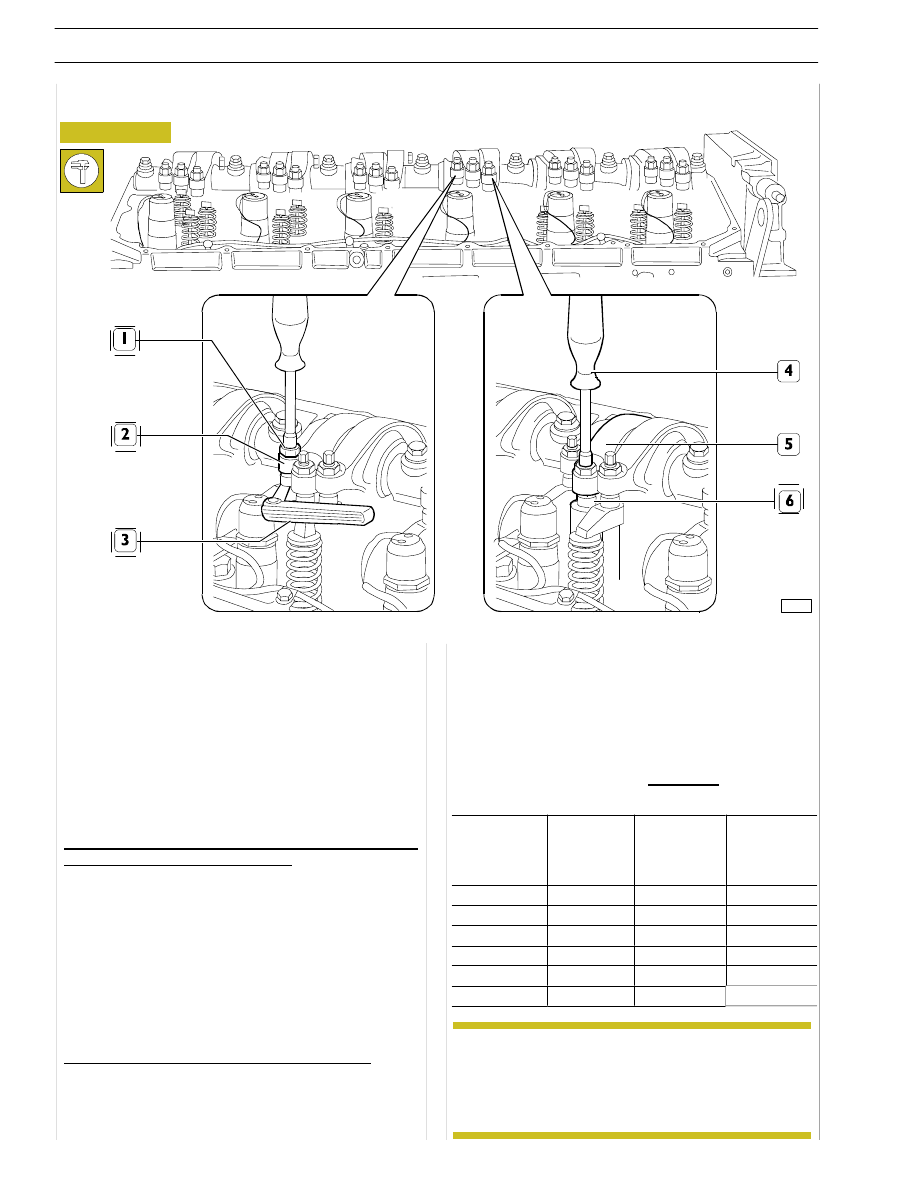
- using an appropriate wrench (4), loosen the
adjustment screw until the pumping element is at the
end-of-stroke;
- tighten the adjustment screw, with a dynamometric
wrench, to 5 Nm tightening torque (0.5 kgm);
- untighten the adjustment screw by 1/2 to 3/4 rotation;
- tighten the locking nut.
FIRING ORDER
1-4-2-6-3-5
The adjustment of clearance between the rockers and rods
controlling the intake and exhaust valves, as well as the
adjustment of pre-loading of the rockers controlling pump
injectors, must be carried out carefully.
Take the cylinder where clearance must be adjusted to the
bursting phase; its valves are closed while balancing the
symmetric cylinder valves.
Symmetric cylinders are 1-6, 2-5 and 3-4.
In order to properly operate, follow these instructions and
data specified on the table.
Adjustment of clearance between the rockers and rods
controlling intake and exhaust valves:
- use a polygonal wrench to slacken the locking nut (1) of
the rocker arm adjusting screw (2).
- insert the thickness gauge blade (3);
- tighten or untighten the adjustment screw with the
appropriate wrench;
- make sure that the gauge blade (3) can slide with a slight
friction;
- lock the nut (1), by blocking the adjustment screw.
Pre-loading of rockers controlling pump injectors:
- using a polygonal wrench, loosen the nut locking the
rocker adjustment screw (5) controlling the pump
injector (6);
ADJUSTMENT OF INTAKE, EXHAUST AND INJECTION ROCKERS
In
order
to
properly
carry
out
the
above-mentioned
adjustments,
follow
the
sequence specified in the table, checking the exact
position in each rotation phase by means of pin
99360612, to be inserted in the 11
th
hole in each
of the three sectors with 18 holes each.
Figure 66
99272
Intake and exhaust rocker play adjustment and pre-loading of rockers controlling pump injectors
NOTE
Нет комментариевНе стесняйтесь поделиться с нами вашим ценным мнением.
Текст