Engine Iveco C10/C13/C78/Cursor 13/Cursor 78. Manual — part 88
72436
Figure 44
Figure 45
Figure 46
Figure 47
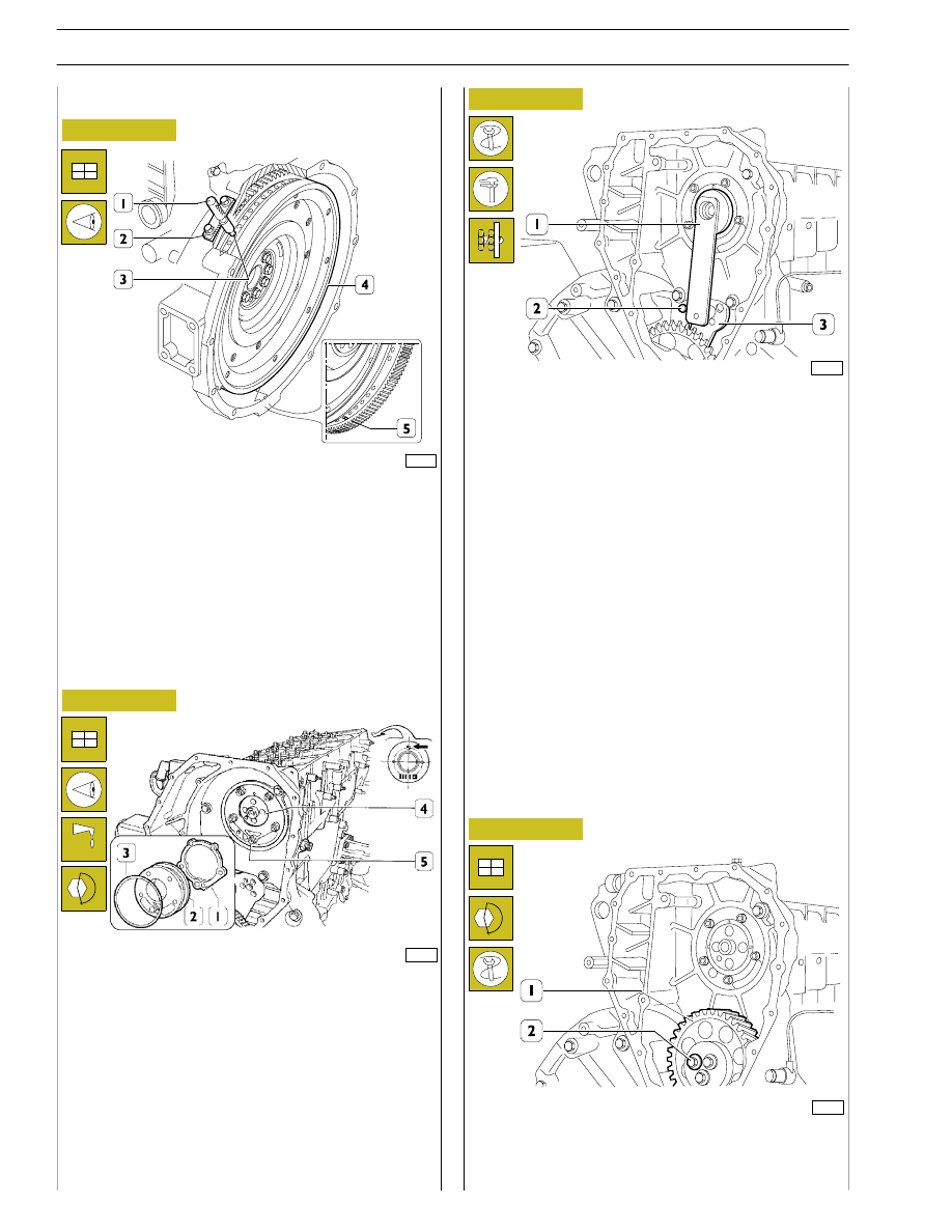
Position the crankshaft with the pistons 1 and 6 at the top dead
centre (T.D.C.).
This situation occurs when:
1.
The hole with reference mark (5) of the engine flywheel
(4) can be seen through the inspection window.
2.
The tool 99360612 (1), through the seat (2) of the engine
speed sensor, enters the hole (3) in the engine flywheel (4).
If this condition does not occur, turn the engine flywheel (4)
appropriately.
Remove the tool 99360612 (1).
- Fit the idle gear (1) back on and lock the screws (2) to the
required torque.
60571
- Apply the gauge 99395219 (1). Check and adjust the
position of the link rod (3) for the idle gear. Lock the screw
(2) to the required torque.
60570
Fit the camshaft (4), positioning it observing the reference
marks (
→) as shown in the figure.
Lubricate the seal (3) and fit it on the shoulder plate (2).
Mount the shoulder plate (2) with the sheet metal gasket (1)
and tighten the screws (5) to the required torque.
73843
Fitting camshaft
16
SECTION 3 - INDUSTRIAL APPLICATION
60572
Figure 48
Figure 49
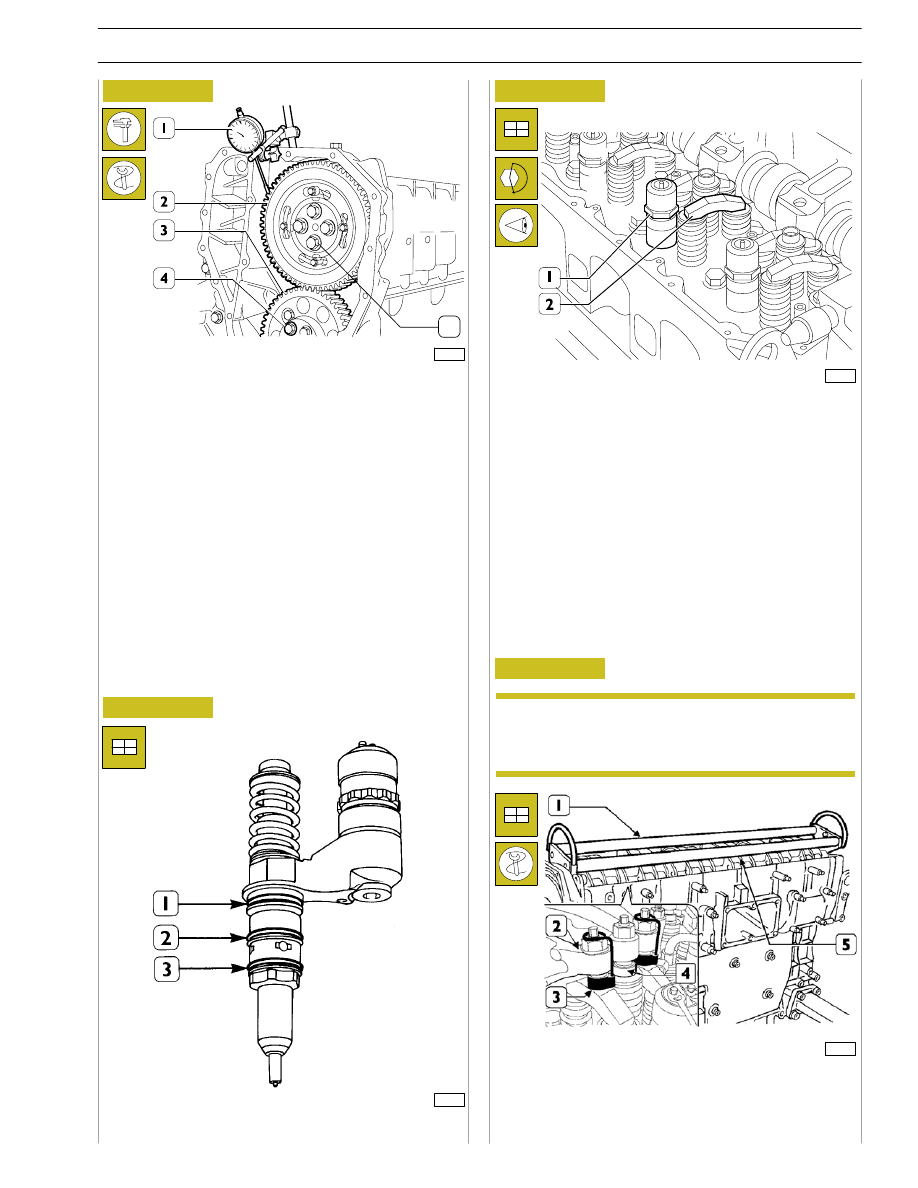
Position the gear (2) on the camshaft so that the 4 slots are
centred with the holes for fixing the camshaft, without fully
locking the screws (5).
Using the dial gauge with a magnetic base (1), check that the
clearance between the gears (2 and 3) is 0.073 — 0.195 mm;
if this is not so, adjust the clearance as follows:
- Loosen the screws (4) fixing the idle gear (3).
- Loosen the screw (2, Figure 46) fixing the link rod. Shift
the link rod (3, Figure 46) to obtain the required
clearance.
- Lock the screw (2, Figure 46) fixing the link rod and
screws (4, Figure 48) fixing the idle gear to the required
torque.
Figure 50
44908
Fit the seals (1) (2) (3) on the injectors.
Before refitting the rocker-arm shaft assembly,
make sure that all the adjustment screws have been
fully unscrewed.
Using tool 99360144 (3), fasten the blocks (4) to the rocker
arms (2).
Apply the tool 99360553 (1) to the rocker arm shaft (5) and
mount the shaft on the cylinder head.
73533
5
Fitting pump-injectors
Fitting rocker-arm shaft assembly
Mount:
- The injectors (1) and, using a torque wrench, lock the
bracket fixing screws to a torque of 26 Nm.
- The crosspieces (2) on the valve stem, all with the largest
hole on the same side.
Figure 51
99284
NOTE
SECTION 3 - INDUSTRIAL APPLICATION
17
18
SECTION 3 - INDUSTRIAL APPLICATION
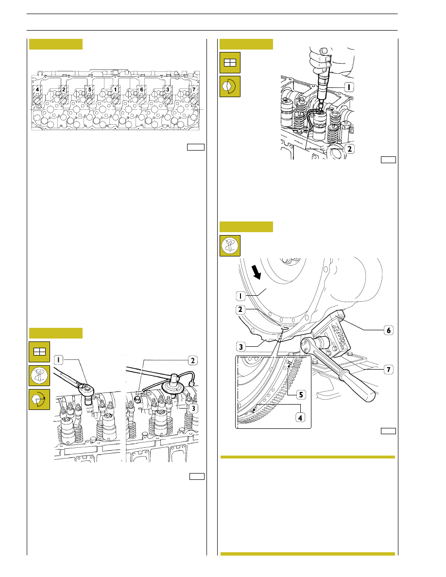
Apply the tool 99360321 (7) and the spacer 99360325 (6) to
the gearbox (3).
Figure 52
Figure 53
45261
Lock the screws (2) fixing the rocker-arm shaft as follows:
- 1
st
phase: tightening to a torque of 80 Nm (8 kgm) with
the torque wrench (1);
- 2
nd
phase: closing with an angle of 60
° using the tool
99395216 (3).
71776
Figure 54
Mount the electric wiring (2), securing it on the
electro-injectors with a torque screwdriver (1) to a torque of
1.36 - 1.92 Nm.
α
The arrow shows the direction of rotation of the
engine when running.
Using the above-mentioned tool, turn the engine
flywheel (1) in the direction of rotation of the
engine so as to take the piston of cylinder no.1 to
approximately the T.D.C. in the phase of
combustion.
This condition occurs when the hole with one
reference mark (4), after the hole with two
reference marks (5) on the engine flywheel (1), can
be seen through the inspection window (2).
71777
Camshaft timing
SCHEME OF SCREW TIGHTENING SEQUENCE
SECURING ROCKER ARMS
Screw screws (1 - 2 - 3) until rocker arms are brought to
contact relating seats on cylinder head, tighten the screws
according to sequence indicated in figure operating in two
steps as indicated in successive figure.
70567A
NOTE
Figure 55
SECTION 3 - INDUSTRIAL APPLICATION
19
71774
60575
Figure 56
Figure 57
Figure 58
Figure 59
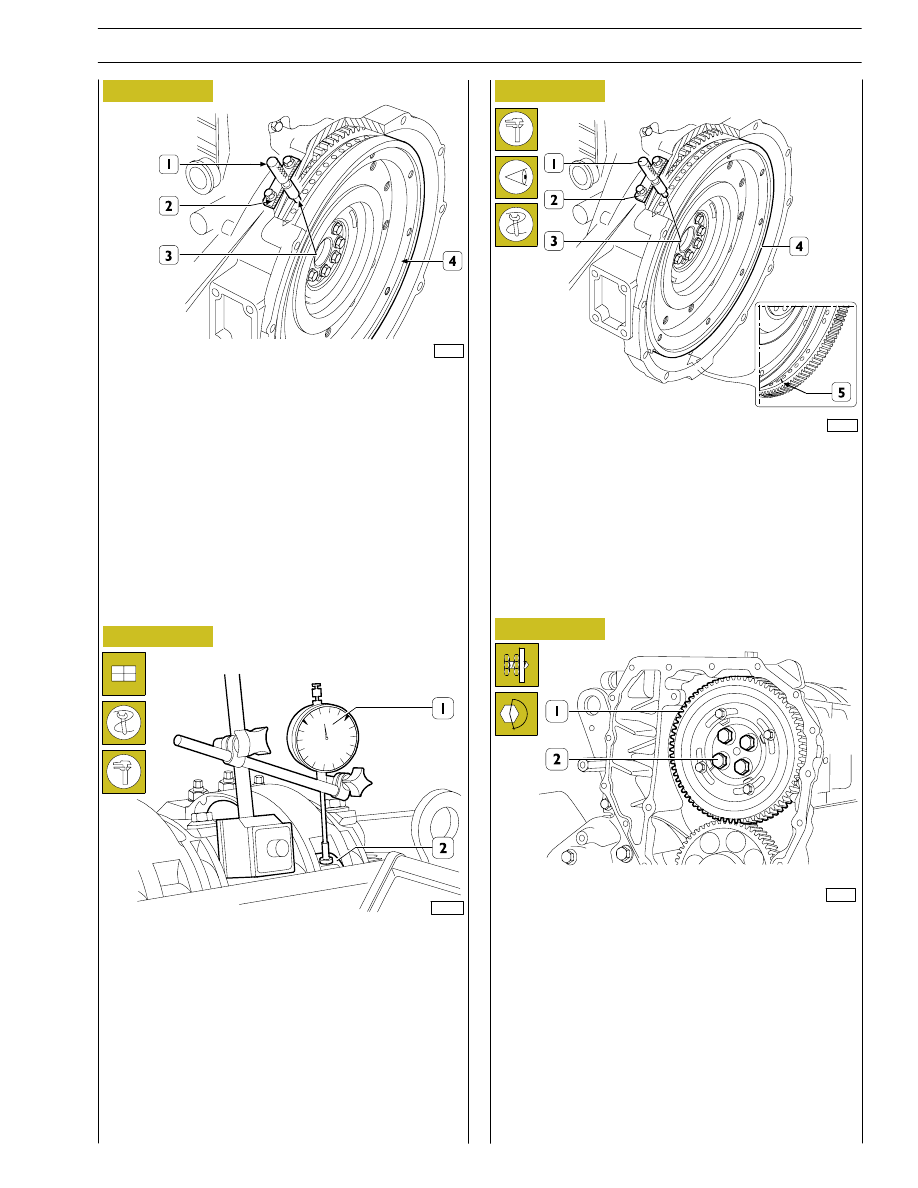
The exact position of piston no.1 at the T.D.C. is obtained
when in the above-described conditions the tool 99360612
(1) goes through the seat (2) of the engine speed sensor into
the hole (3) in the engine flywheel (4).
If this is not the case, turn and adjust the engine flywheel (4)
appropriately.
Remove the tool 99360612 (1).
Set the dial gauge with the magnetic base (1) with the rod on
the roller (2) of the rocker arm that governs the injector of
cylinder no.1 and pre-load it by 6 mm.
With tool 99360321 (7) Figure 54, turn the crankshaft
clockwise until the pointer of the dial gauge reaches the
minimum value beyond which it can no longer fall.
Reset the dial gauge.
Turn the engine flywheel anticlockwise until the dial gauge gives
a reading for the lift of the cam of the camshaft of 4.44
±0.05 mm.
The camshaft is in step if at the cam lift values of 4.44
±0.05 mm
there are the following conditions:
1) the hole marked with a notch (5) can be seen through the
inspection window;
2) the tool 99360612 (1) through the seat (2) of the engine
speed sensor goes into the hole (3) in the engine
flywheel (4).
If you do not obtain the conditions illustrated in Figure 58 and
described in points 1 and 2, proceed as follows:
1) loosen the screws (2) securing the gear (1) to the camshaft
and utilize the slots (see Figure 60) on the gear (1);
2) turn the engine flywheel appropriately so as to bring about
the conditions described in points 1 and 2 Figure 58, it
being understood that the cam lift must not change at all;
3) lock the screws (2) and repeat the check as described
above.
Tighten the screws (2) to the required torque.
77259
106535
Нет комментариевНе стесняйтесь поделиться с нами вашим ценным мнением.
Текст