Engine Iveco C10/C13/C78/Cursor 13/Cursor 78. Manual — part 89
20
SECTION 3 - INDUSTRIAL APPLICATION
71778
72436
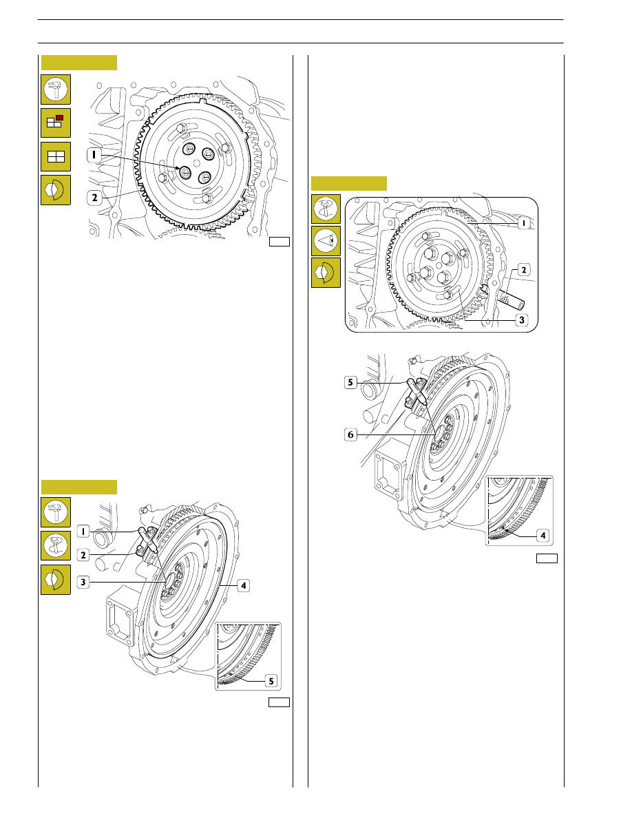
Figure 60
When the adjustment with the slots (1) is not enough to make
up the phase difference and the camshaft turns because it
becomes integral with the gear (2); as a result, the reference
value of the cam lift varies, in this situation it is necessary to
proceed as follows:
1) lock the screws (2, Figure 59) and turn the engine flywheel
clockwise by approx. 1/2 turn;
2) turn the engine flywheel anticlockwise until the dial gauge
gives a reading of the lift of the cam of the camshaft of 4.44
±0.05 mm;
3) take out the screws (2, Figure 59) and remove the gear (1)
from the camshaft.
Turn the flywheel (4) again to bring about the following
conditions:
- a notch (5) can be seen through the inspection window;
- the tool 99360612 (1) inserted to the bottom of the seat
of the engine speed sensor (2) and (3).
77260
Phonic wheel timing
Turn the crankshaft by taking the piston of cylinder no. 1 into
the compression phase at T.D.C.; turn the flywheel in the
opposite direction to the normal direction of rotation by
approximately 1/4 of a turn.
Again turn the flywheel in its normal direction of rotation until
you see the hole marked with the double notch (4) through
the inspection hole under the flywheel housing. Insert tool
99360612 (5) into the seat of the flywheel sensor (6).
Insert the tool 99360613 (2), via the seat of the phase sensor,
onto the tooth obtained on the phonic wheel.
Should inserting the tool (2) prove difficult, loosen the screws
(3) and adjust the phonic wheel (1) appropriately so that the
tool (2) gets positioned on the tooth correctly. Go ahead and
tighten the screws (3).
Mount the gear (2) Figure 60 with the 4 slots (1) centred with
the fixing holes of the camshaft, locking the relevant screws to
the required tightening torque.
Check the timing of the shaft by first turning the flywheel
clockwise to discharge the cylinder completely and then turn
the flywheel anticlockwise until the dial gauge gives a reading
of 4.44
±0.05.
Check the timing conditions described in Figure 58.
Figure 61
Figure 62
SECTION 3 - INDUSTRIAL APPLICATION
21
Clockwise
start-up
and rotation
Adjusting
cylinder
valve no.
Adjusting
clearance
of cylinder
valve no.
Adjusting
pre-loading
of cylinder
injector no.
1 and 6 at TDC
6
1
5
120º
3
4
1
120º
5
2
4
120º
1
6
2
120º
4
3
6
120º
2
5
3
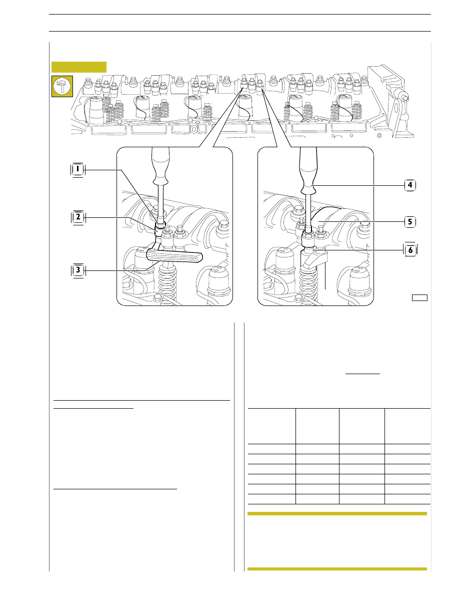
- Lock the adjusting screw to a torque of 5 Nm (0.5 kgm)
by means of a torque wrench.
- Back off the adjusting screw 1/2 to 3/4 turn.
- Tighten the lock nut.
FIRING ORDER
1-4-2-6-3-5
Adjustment of clearances between rockers and valve studs
and preloading of pump injector rockers should be carried out
with extreme care.
Bring the cylinder under examination to the firing stage, the
valves of this cylinder remain closed while the valves of the
other cylinder in the pair can be adjusted.
The cylinder pairs are 1-6,2-5,3-4.
Strictly adhere to directions and data given on the table below.
Adjusting
clearances
between
rockers
and
intake/exhaust/valve studs:
- Use a box wrench to loosen the adjusting screw locking
nut (1).
- Insert the feeler gauge blade (3).
- Use a suitable wrench to screw the adjusting screw in or
out as required.
- Ensure the feeler gauge blade (3) can slide between the
parts concerned with a slight friction.
- Hold the screw still while tightening the nut (1).
Setting pump-injector rocker preloading:
- Use a box wrench to loosen the nut fastening the
adjusting
screw
for
rocker
arm
(5)
controlling
pump-injector (6).
- With a suitable wrench (4) tighten the adjusting screw
until the pumping element reaches its-end-of-stroke
point.
ADJUSTING INTAKE/EXHAUST ROCKERS AND INJECTION
In order to properly carry out the above-mentioned
adjustments, follow the sequence specified in the
table, checking the exact position in each rotation
phase by means of pin 99360612, to be inserted in
the 11
th
hole in each of the three sectors with 18
holes each.
Figure 63
99272
Intake and exhaust rocker play adjustment and pre-loading of rockers controlling pump injectors
NOTE
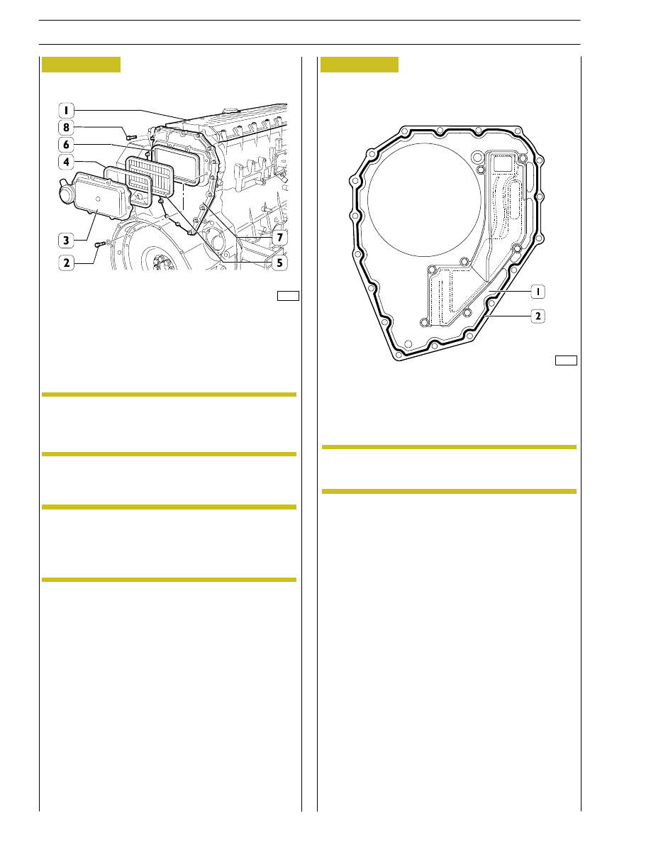
Apply silicone LOCTITE 5970 IVECO No. 2992644 on the
blow-by case and form a string (2) of
∅ 1,5 ±,
as shown
in the figure.
Fit the blow-by case (1) within 10’ from sealer
application.
Fit the cover (3) and tighten the fastening screws (2) to the
prescribed torque.
The filter (5) operation is unidirectional, therefore
it must be assembled with the two sight supports
as illustrated in the figure.
Fit the distribution cover (1).
Fit the blow-by case (7) and its gasket and then tighten the
screws (8) to the prescribed torque.
Install the filter (5) and the gaskets (4 and 6).
Figure 64
Figure 65
Apply silicone LOCTITE 5970 IVECO n˚ 2992644
on the blow-by case (7) surface of engines fitted
with P.T.O. according to the procedure described
in the following figure.
85480
85481
0.5
0.2
.
NOTE
NOTE
NOTE
22
SECTION 3 - INDUSTRIAL APPLICATION
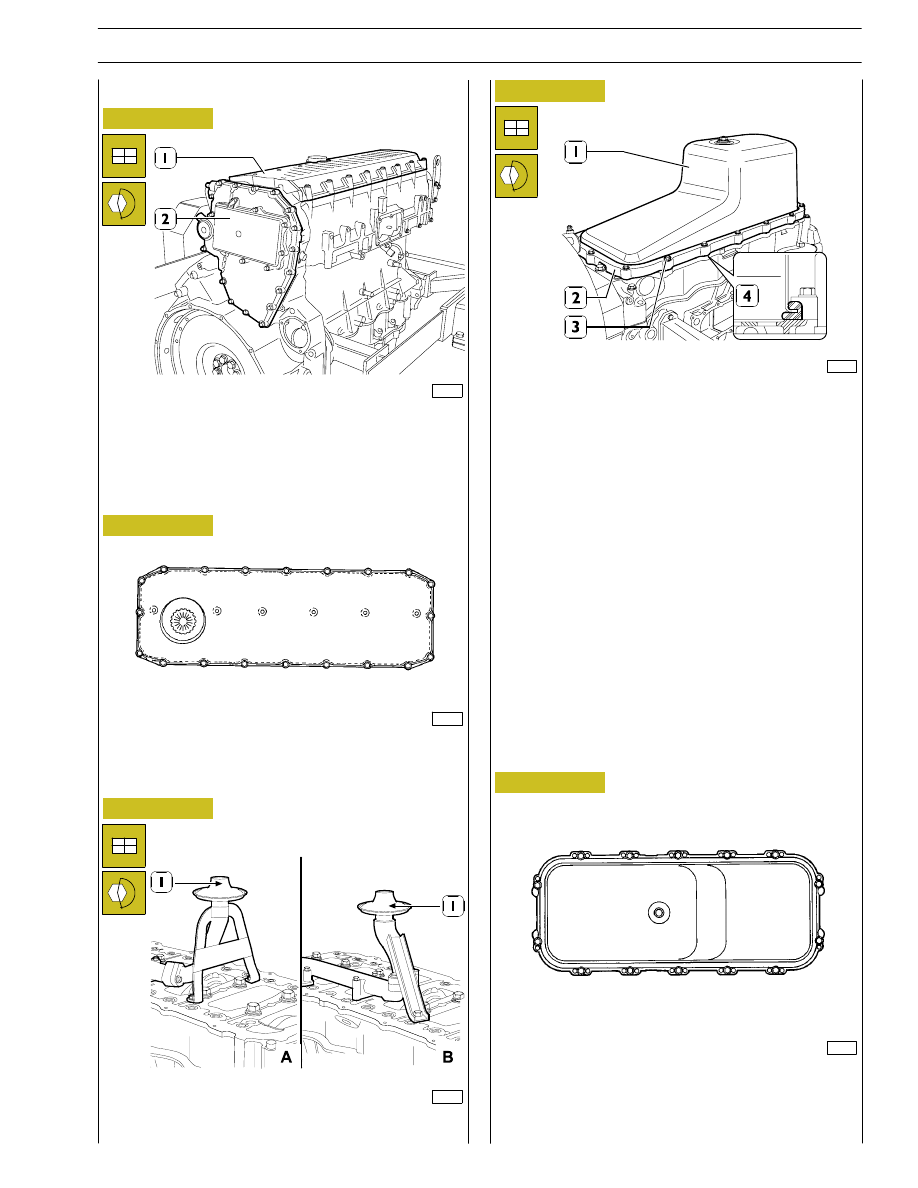
ENGINE COMPLETION
Place gasket (4) on oil sump (1), position spacer (2) and fit the
sump onto the engine base by tightening screws (3) to the
specified torque, by complying with the tightening sequence
indicated in Figure 70.
Fit valve rocker arm cover (1) to the specified torque, by
following the tightening sequence indicated in Figure 67.
Fit the suction strainer (1) and tighten the fixing screws to the
prescribed torque.
Figure 66
Figure 67
99368
Figure 68
Figure 69
45363
101606
DIAGRAM OF ENGINE OIL SUMP FIXING SCREWS
TIGHTENING SEQUENCE
1
8
12
11
10
3
9
13
14
4
5
6
7
2
45362
17
14
13
1
4
5
8
18
19
20
16
15
12
2
3
6
7
11
10
9
DIAGRAM OF ROCKER ARM CAP FIXING SCREWS
TIGHTENING SEQUENCE
81872
Figure 70
SECTION 3 - INDUSTRIAL APPLICATION
23
Нет комментариевНе стесняйтесь поделиться с нами вашим ценным мнением.
Текст