Engine Iveco C10/C13/C78/Cursor 13/Cursor 78. Manual — part 27
47595
47596
Figure 41
Figure 42
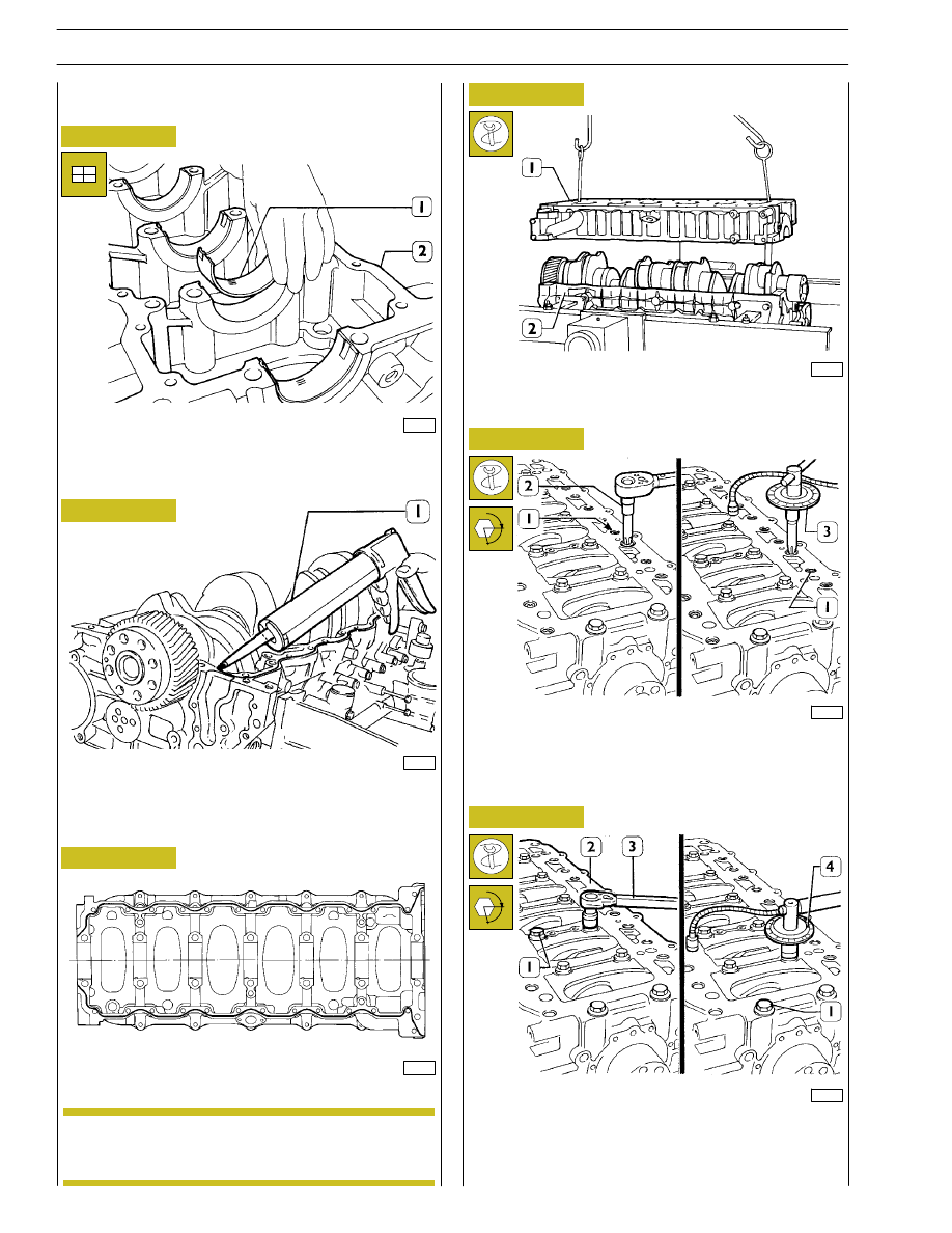
Place the half-bearings (1) on the main bearings in the
underblock (2).
Remove the underbase.
By means of suitable equipment (1) apply silicone LOCTITE
5970 IVECO No. 2992644 to the block, as shown in the
figure.
Sealant application diagram
Fit the underblock within 10’ of the application of
the sealant.
Figure 43
49021
47581
Figure 44
Figure 45
Fit the sub-engine block and use a dynamometric wrench (2)
to tighten the outer hexagonal-grooved screws (1) to 25 Nm
according to the diagrams on the following page.
Fit the underblock by means of a suitable hoist and hooks (1).
49022
α
Figure 46
Close the inner screws (1) to 140 Nm torque by means of
a dynamometric wrench (3), then with two further angular
phases 60
° + 60°, using tool 99395216 (4). Tighten again the
outer screws (1, Figure 45) with 90
° angular closing, using
tool 99395215 (3, Figure 45).
α
47579
ASSEMBLING
THE
ENGINE
ON
THE
BENCH
NOTE
26
SECTION 4 - OVERHAUL AND TECHNICAL SPECIFICATIONS
44898
FRONT SIDE
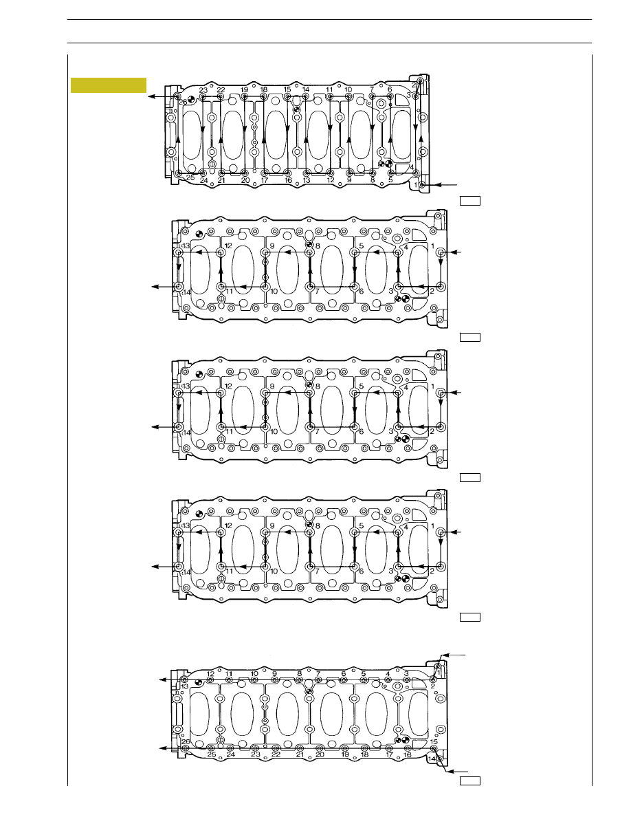
Fourth phase:
inner screws
angle closing
(60º)
44897
44899
44898
Figure 47
First phase: outer
screws preliminary
tightening
(25 Nm)
FRONT SIDE
FRONT SIDE
FRONT SIDE
Second phase:
inner screws
preliminary
tightening
(140 Nm)
Fifth phase:
outer screws
angle closing
(90º)
44898
FRONT SIDE
Third phase:
inner screws
angle closing
(60º)
DIAGRAM SHOWING THE UNDERBLOCK FIXING SCREWS TIGHTENING ORDER
SECTION 4 - OVERHAUL AND TECHNICAL SPECIFICATIONS
27
Make sure the piston does show any trace of seizing, scoring,
cracking; replace as necessary.
49023
47580
Figure 48
Figure 49
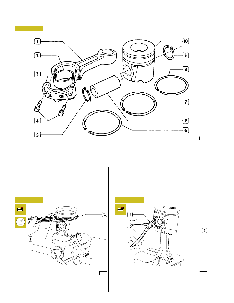
PISTON CONNECTING ROD ASSEMBLY
1. Connecting rod body - 2. Half bearings - 3. Connecting rod cap - 4. Cap fastening screws - 5. Split ring - 6. Scraper ring with
spiral spring - 7. Bevel cut sealing ring - 8. Trapezoidal sealing ring - 9. Piston pin - 10. Piston
Removal of the piston split rings (2) using the pliers 99360184
(1).
Removal
Pistons are equipped with three elastic rings: a sealing ring, a
trapezoidal ring and a scraper ring.
Pistons are grouped into classes A and B for diameter.
49024
Figure 50
Remove the piston pin split rings (2) using the round tipped
pliers (1).
PISTON-CONNECTING ROD ASSEMBLY
28
SECTION 4 - OVERHAUL AND TECHNICAL SPECIFICATIONS
49025
32618
49026
Figure 51
Figure 52
Figure 53
Figure 54
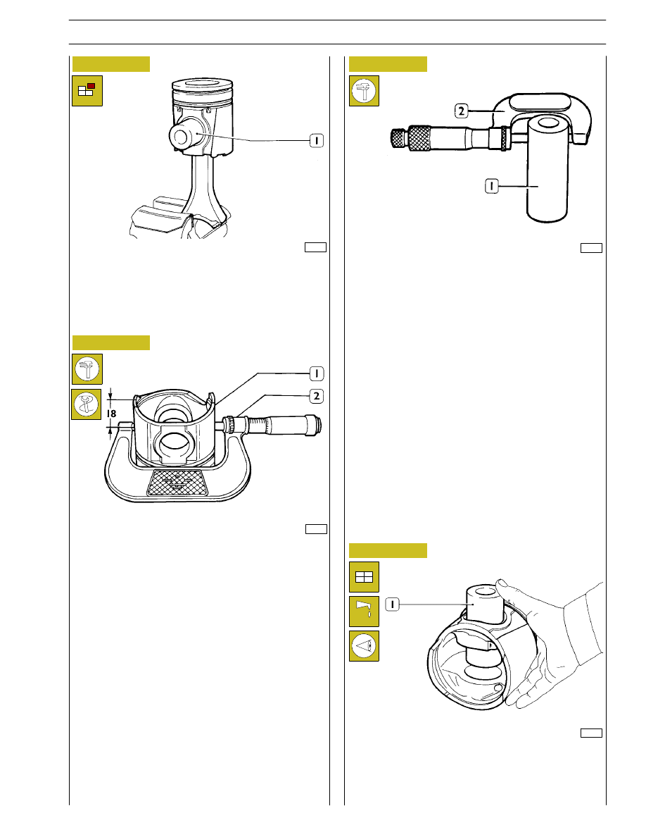
Remove the piston pin (1).
If removal is difficult use the appropriate beater.
Measuring the diameter of the pistons
Measuring the gudgeon pin diameter (1) with a micrometer
(2).
Conditions for correct gudgeon pin-piston
coupling
Lubricate the pin (1) and the relevant housing on the piston
hubs with engine oil; piston must be inserted with a slight
finger pressure and it should not come out by gravity.
47584
Using a micrometer (2), measure the diameter of the piston
(1) to determine the assembly clearance; the diameter should
be measured at the specified value.
SECTION 4 - OVERHAUL AND TECHNICAL SPECIFICATIONS
29
Нет комментариевНе стесняйтесь поделиться с нами вашим ценным мнением.
Текст