Engine Iveco C10/C13/C78/Cursor 13/Cursor 78. Manual — part 26
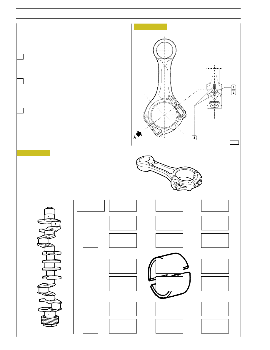
Figure 29
SELECTING THE BIG END BEARING SHELLS
(JOURNALS WITH NOMINAL DIAMETER)
There are three markings on the body of the connecting rod
in the position shown in the view from ”A”:
1
2
3
The number, indicating the class of diameter of the bearing
shell seat may be 1, 2 o 3.
Determine the type of big end bearing to fit on each journal
by following the indications in the table (Figure 30).
47557
VIEW FROM “A”
STD.
1
2
3
1
2
3
green
green
red
red
red
red
red
red
green
green
green
green
green
green
green
green
red
red
Class
Figure 30
Letter indicating the class of weight:
A
=
2865 to 2895 g.
B
=
2896 to 2925 g.
C
=
2926 to 2955 g.
Number indicating the selection of the diameter of the
big end bearing seat:
1
=
77.000 to 77.010 mm
2
=
77.011 to 77.020 mm
3
=
77.021 to 77.030 mm
Numbers identifying the cap-connecting rod coupling.
22
SECTION 4 - OVERHAUL AND TECHNICAL SPECIFICATIONS
green/black
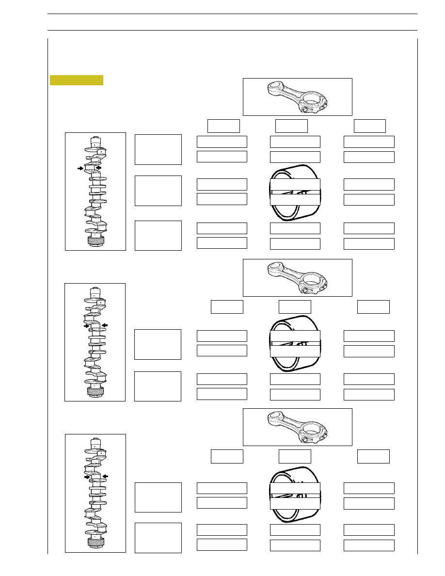
Selection of connecting rod half-bearings (rectified pins)
If pins have been rectified, the procedure described must be applied.
In this case, (for each undersizing) determine the tolerance field the new big end pins belong to, and install the half-bearings
identified according to the relative table.
-0.127
1
2
3
72.789
72.798
green/black
green/black
green/black
green/black
green/black
green/black
red/black
red/black
green/black
green/black
green/black
red/black
red/black
red/black
red/black
green/black
green/black
72.799
72.808
72.809
72.818
1
2
3
red/black =
2.074 to 2.083 mm
green/black =
2.063 to 2.073 mm
-0.254
1
2
3
72.671
72.680
red
green
green
red
green
green
red
2.127 to 2.137 mm
green =
2.138 to 2.147 mm
-0.508
1
2
3
72.417
72.426
red
green
green
red
green
green
red
red
green
red
red
green
72.427
72.437
red
red
green
red
red
green
red
=
2.254 to 2.264 mm
green =
2.265 to 2.274 mm
72.681
72.691
Figure 31
SECTION 4 - OVERHAUL AND TECHNICAL SPECIFICATIONS
23
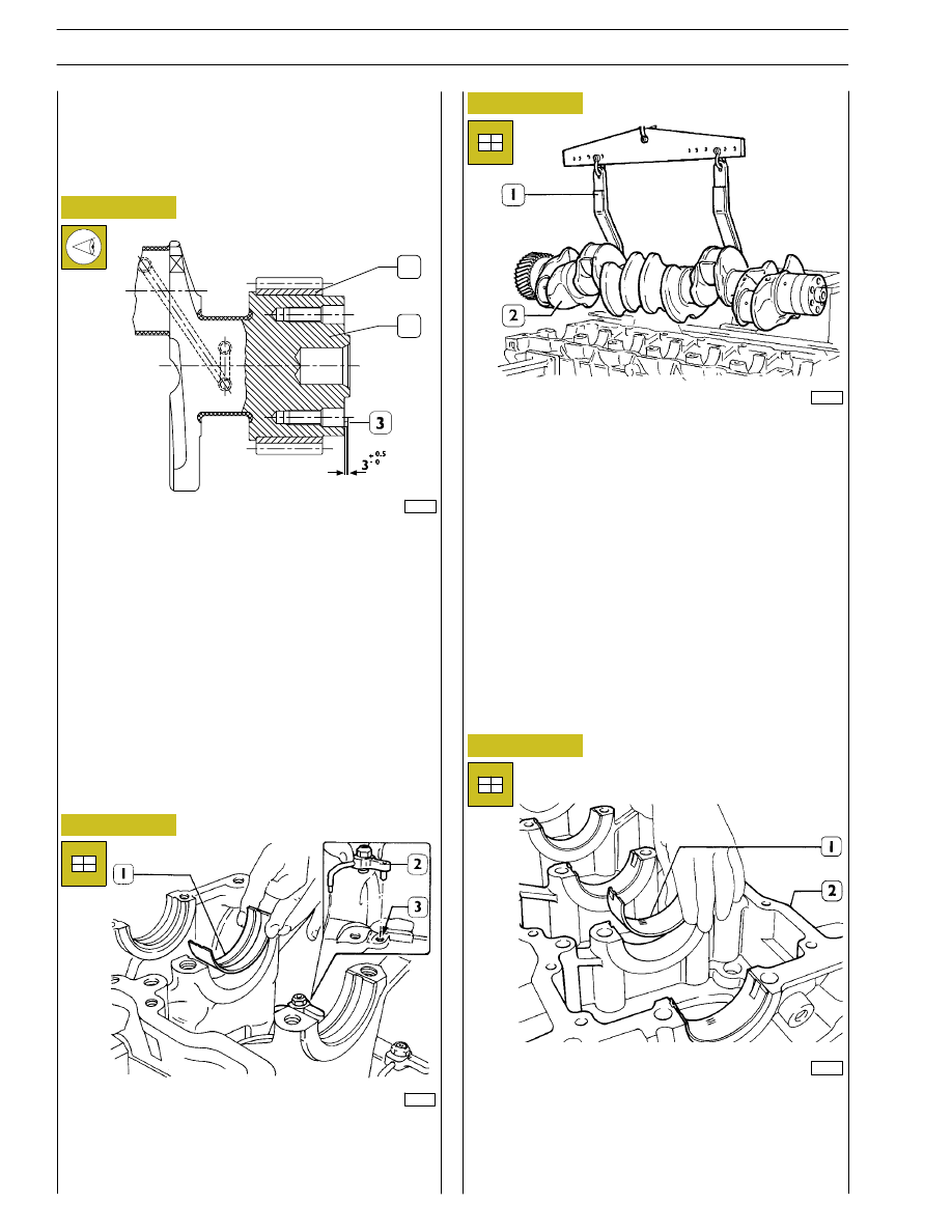
Install the half-bearings (1) on the main bearings in the
underblock (2).
Check the installation clearance between the main journals
and the relative bearings as follows:
Using the hoist and hook 99360500 (1) mount the driving
shaft (2).
After fitting the gear (1) on the crankshaft (2), heat it for
~15 minutes in an oven at temperature not higher than
180
°C.
Let them cool down after the installation.
If changing the pin (3), after fitting it on, check it protrudes
from the crankshaft as shown in the figure.
49020
47579
47578
49021
Figure 32
Figure 33
Figure 34
Figure 35
Install the oil spray nozzles (2) and have the dowel coincide
with the block hole (3).
Install the half-bearings (1) on the main bearings.
Replacing the timing control gear and the oil
pump
Check that the teeth of the gears are not damaged or worn,
otherwise remove them using the appropriate extractor.
Checking main journal installation clearance
1
2
24
SECTION 4 - OVERHAUL AND TECHNICAL SPECIFICATIONS
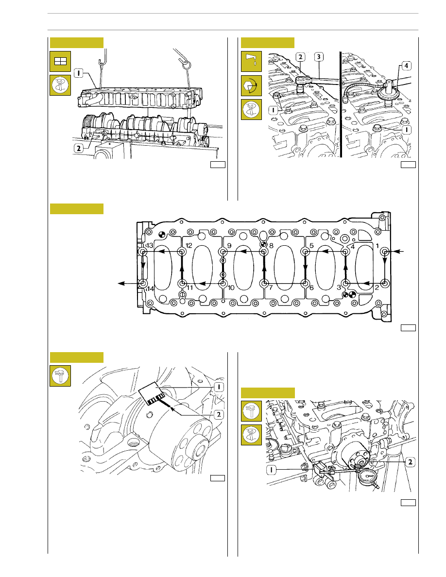
End float is checked by placing a magnetic dial gauge (1) on
the crankshaft (2), as shown in the figure. If the value obtained
is higher than specified, replace the rear thrust half-bearings
and repeat this check.
- Lubricate inside screws (1) con UTDM oil, and tighten
them by dynamometric wrench to 140 Nm torque, thus
with 60º+60º angle closing, by following the diagram
below.
Place a piece of calibrated wire on the journal of the
crankshaft (2), parallel to the longitudinal axis; install the
underblock (1), by hoist and appropriate hooks.
49022
47579
47578
47588
44898
Figure 36
Figure 37
Figure 38
Figure 39
Figure 40
- Remove the under-block
The clearance between the main bearings and the journals
is obtained by comparing the calibrated wire length (2) at the
maximum deflection point, with the calibrated scale on the
coating (1) containing the calibrated wire (1).
Numbers shown on the scale specify the clearance in
coupling millimeters. If the clearance obtained is different
from the clearance required, replace the half-bearings and
repeat this check.
FRONT SIDE
Diagram showing the tightening order of the screws fixing the lower under-block to the block
Checking crankshaft end float
α
SECTION 4 - OVERHAUL AND TECHNICAL SPECIFICATIONS
25
Нет комментариевНе стесняйтесь поделиться с нами вашим ценным мнением.
Текст