Engine Iveco C10/C13/C78/Cursor 13/Cursor 78. Manual — part 28
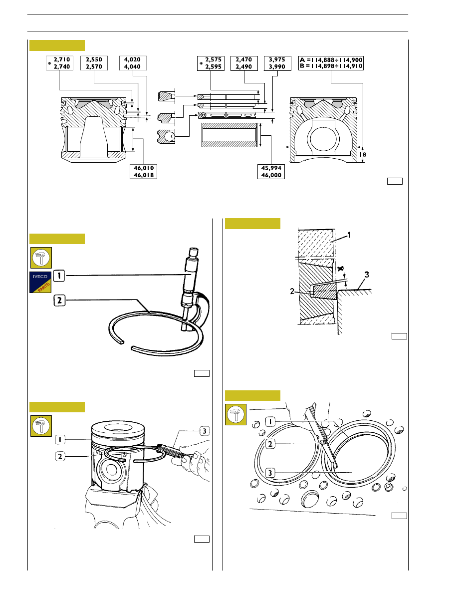
MAIN DATA ON PISTONS, AND PISTONS RINGS
* Values are determined on
∅ of 112 mm.
16552
3513
Figure 55
Check the thickness of the piston ring (2) using a micrometer
(1).
The sealing ring (2) of the 1º cavity is trapezoidal. Clearance
“X” between the sealing ring and its housing is measured by
placing the piston (1) with its ring in the cylinder barrel (3),
so that the sealing ring is half-projected out of the cylinder
barrel.
Piston rings
77816
16552
Check the clearance between the sealing rings (2) and the
relative piston housings (1) using a thikness gauge (3).
36134
Check the opening between the ends of the sealing rings (1),
using a thickness gauge (2), entered in the cylinder barrel (3).
If the distance between ends is lower or higher than the value
required, replace split rings.
Figure 56
Figure 57
Figure 58
Figure 59
30
SECTION 4 - OVERHAUL AND TECHNICAL SPECIFICATIONS

47557
44927
Figure 60
Figure 61
MAIN DATA - BUSH, CONNECTING ROD, PIN AND HALF-BEARINGS
* Values to be obtained after installing the bush
DIAGRAM CONNECTING ROD MARKS
Letter indicating the weight class:
A
=
2865 to 2895 g.
B
=
2896 to 2925 g.
C
=
2926 to 2955 g.
Number indicating the selection of diameter for
the big end bearing housing:
1
=
77.000 to 77.010 mm
2
=
77.011 to 77.020 mm
3
=
77.021 to 77.030 mm
Numbers identifying cap-connecting rod coupling
1
2
3
Data concerning the class section of connecting rod
housing and weight are stamped on the big end.
When installing connecting rods, make sure
they all belong to the same weight class.
VIEW FROM “A”
CONNECTING ROD
NOTE
SECTION 4 - OVERHAUL AND TECHNICAL SPECIFICATIONS
31
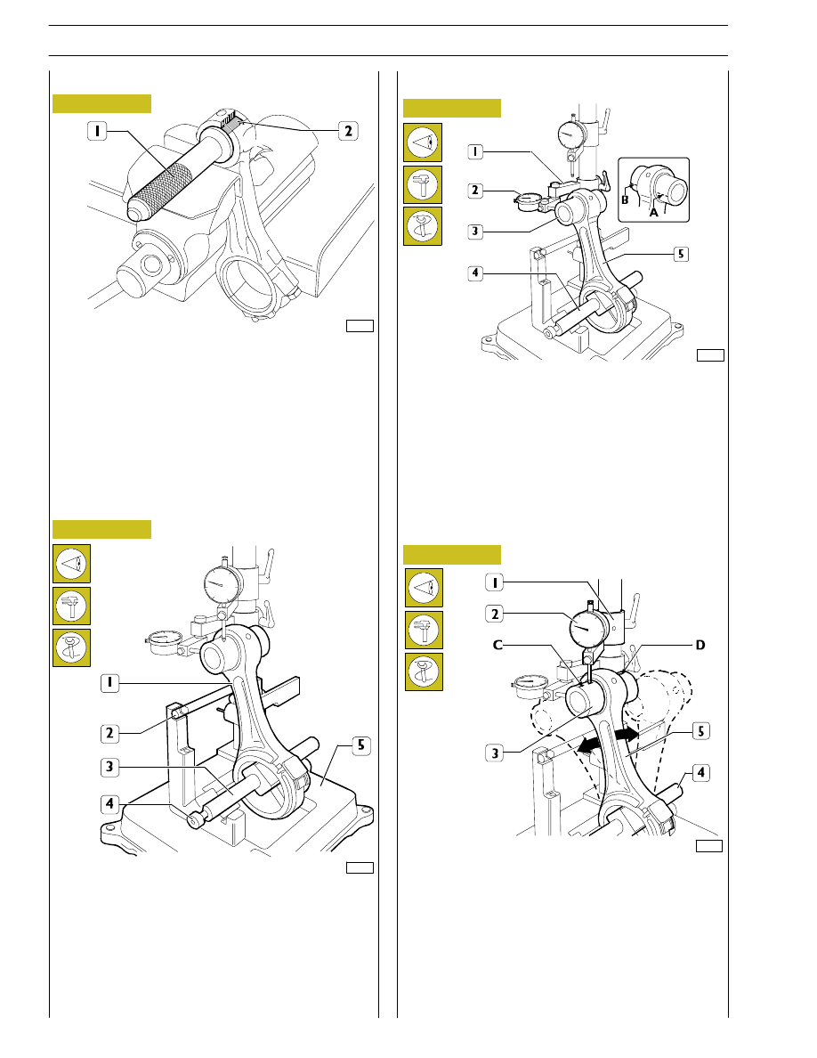
Check the torsion of the connecting rod (5) by comparing
two points (A and B) of the pin (3) on the horizontal plane
of the axis of the connecting rod.
Position the mount (1) of the dial gauge (2) so that this
pre-loads by approx. 0.5 mm on the pin (3) at point A and
zero the dial gauge (2). Shift the spindle (4) with the
connecting rod (5) and compare any deviation on the
opposite side B of the pin (3): the difference between A and
B must be no greater than 0.08 mm.
Check the bending of the connecting rod (5) by comparing
two points C and D of the pin (3) on the vertical plane of the
axis of the connecting rod.
Position the vertical mount (1) of the dial gauge (2) so that this
rests on the pin (3) at point C.
Swing the connecting rod backwards and forwards seeking the
highest position of the pin and in this condition zero the dial
gauge (2). Shift the spindle (4) with the connecting rod (5) and
repeat the check on the highest point on the opposite side D
of the pin (3). The difference between point C and point D
must be no greater than 0.08 mm.
61695
61696
Checking axis alignment
Check the alignment of the axes of the connecting rods (1)
with device 99395363 (5), proceeding as follows:
Fit the connecting rod (1) on the spindle of the tool
99395363 (5) and lock it with the screw (4).
Set the spindle (3) on the V-prisms, resting the connecting
rod (1) on the stop bar (2).
Figure 62
Figure 63
Figure 64
Checking torsion
61694
Checking bending
Checking connecting rods
73535
Check the bushing in the small end has not come loose and
shows no sign of scoring or seizure; replace it if it does.
The bushing (2) is removed and fitted with a suitable drift (1).
When driving it in, make absolutely sure that the holes for the
oil to pass through in the bushing and small end coincide.
Using a boring machine, rebore the bushing so as to obtain
a diameter of 46.015 — 46.030.
Figure 65
Bushings
32
SECTION 4 - OVERHAUL AND TECHNICAL SPECIFICATIONS

SECTION 4 - OVERHAUL AND TECHNICAL SPECIFICATIONS
33
1
2
3
73536
74052
60614
49030
Figure 66
Figure 67
Figure 68
Figure 69
The piston (1) has to be fitted on the connecting rod (2) so
that the graphic symbol (4), showing the assembly position
in the cylinder liner, and the punch marks (3) on the
connecting rod are observed as shown in the figure.
Fit the pin (2) and fasten it on the piston (1) with the split rings
(3).
To fit the piston rings (1) on the piston (2) use the pliers
99360184 (3).
The rings need to be mounted with the word ”TOP” (4)
facing upwards. Direct the ring openings so they are
staggered 120
° apart.
Fit the bearing shells (1), selected as described under the
heading ”Selecting the main and big end bearing shells”, on
both the connecting rod and the cap.
If reusing bearing shells that have been removed, fit them
back into their respective seats in the positions marked
during removal.
Mounting the connecting rod — piston assembly
Mounting the piston rings
Fitting the big end bearing shells
Нет комментариевНе стесняйтесь поделиться с нами вашим ценным мнением.
Текст