Engine Iveco C10/C13/C78/Cursor 13/Cursor 78. Manual — part 90
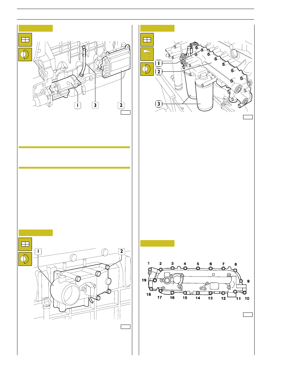
Figure 71
Fit the intake manifold (1) and tighten the fixing screws (2) to the
prescribed torque.
Figure 72
Figure 73
Figure 74
99264
Tightening the fixing screws to the prescribed torque, mount:
-
the starter motor (1);
-
the control unit (2) and its support;
-
the oil dipstick (3) in the crankcase.
Check the state of the flexible elements of the
control unit support and change them if they have
deteriorated.
99263
Fit heat exchanger (2) with its respective gasket, then tighten
fastening screws (1) to the torque specified and according to
the sequence indicated in Figure 74.
Fit the oil filters (1) on the relevant supports as follows:
-
oil the seals;
-
screw the filters down for the seals to make contact with
the supporting bases;
-
tighten the filters to a torque of 35 to 40 Nm.
101605
455361
DIAGRAM OF HEAT EXCHANGER FIXING SCREWS
TIGHTENING SEQUENCE
NOTE
24
SECTION 3 - INDUSTRIAL APPLICATION
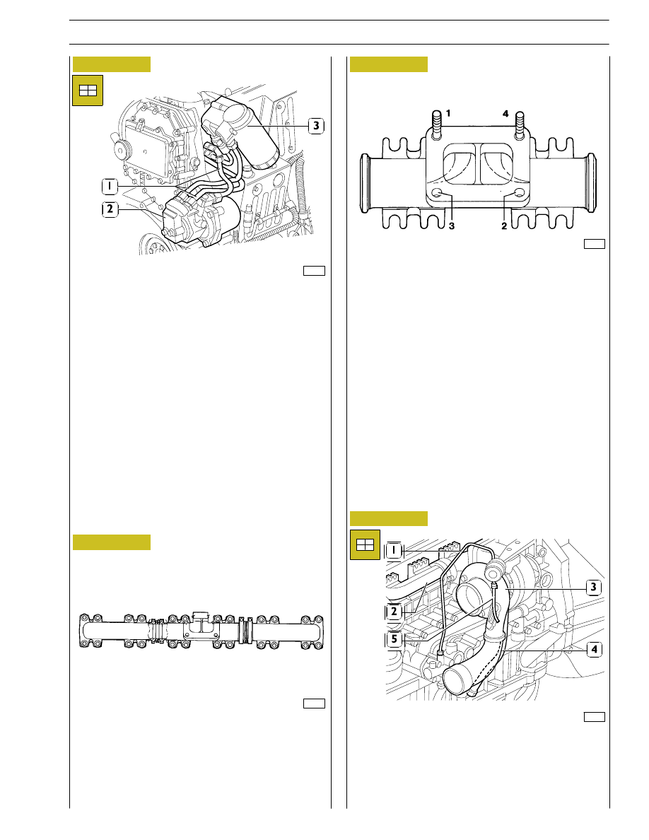
Fit, with the respective gaskets.
-
the fuel pump (2);
-
fuel filter unit (3) with its respective pipes (1);
-
connect the pipes (1) to the fuel pump (2).
99273
Figure 75
Figure 76
Figure 77
Mount the following with new seals:
-
exhaust manifold (2);
-
turbocharger (3);
-
oil pipe (1 and 4);
-
pipe to the actuator (5).
99274
Figure 78
DIAGRAM OF EXHAUST MANIFOLD FIXING SCREWS
TIGHTENING SEQUENCE
DIAGRAM OF TURBOCHARGER FIXING SCREWS AND
NUTS TIGHTENING SEQUENCE
SEQUENCE: Preliminary tightening
4 - 3 - 1 - 2
Tightening
1 - 4 - 2 - 3
45359
1
8
6
3
2
7
6
3
4
7
6
3
2
7
5
4
8
5
2
8
5
4
1
1
45360
SECTION 3 - INDUSTRIAL APPLICATION
25
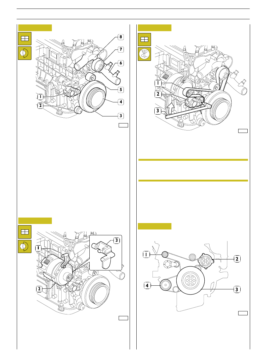
Figure 79
Figure 80
Fit, with the following parts:
-
automatic tightener support (1);
-
automatic tightener (2);
-
damper flywheel (3) and pulley beneath;
-
fixed tightener (5);
-
water pump (7);
-
the pulley (4);
-
pipe comprehensive of coolant (6);
-
thermostat assembly (8).
Figure 81
Mount the following, tightening the screws to the prescribed
torque:
-
the supports (1 and 3);
-
alternator (2).
Using a suitable tool (3), work in the direction of the arrow on
the tightener (2) and mount the belt (1).
The tighteners are automatic, so there are no other
adjustments after assembly.
99360
99256
99359
DIAGRAM FOR FITTING BELT DRIVING FAN - WATER
PUMP - ALTERNATOR
1. Alternator - 2. Water pump - 3. Crankshaft -
4. Compressor.
Figure 82
101701
NOTE
26
SECTION 3 - INDUSTRIAL APPLICATION
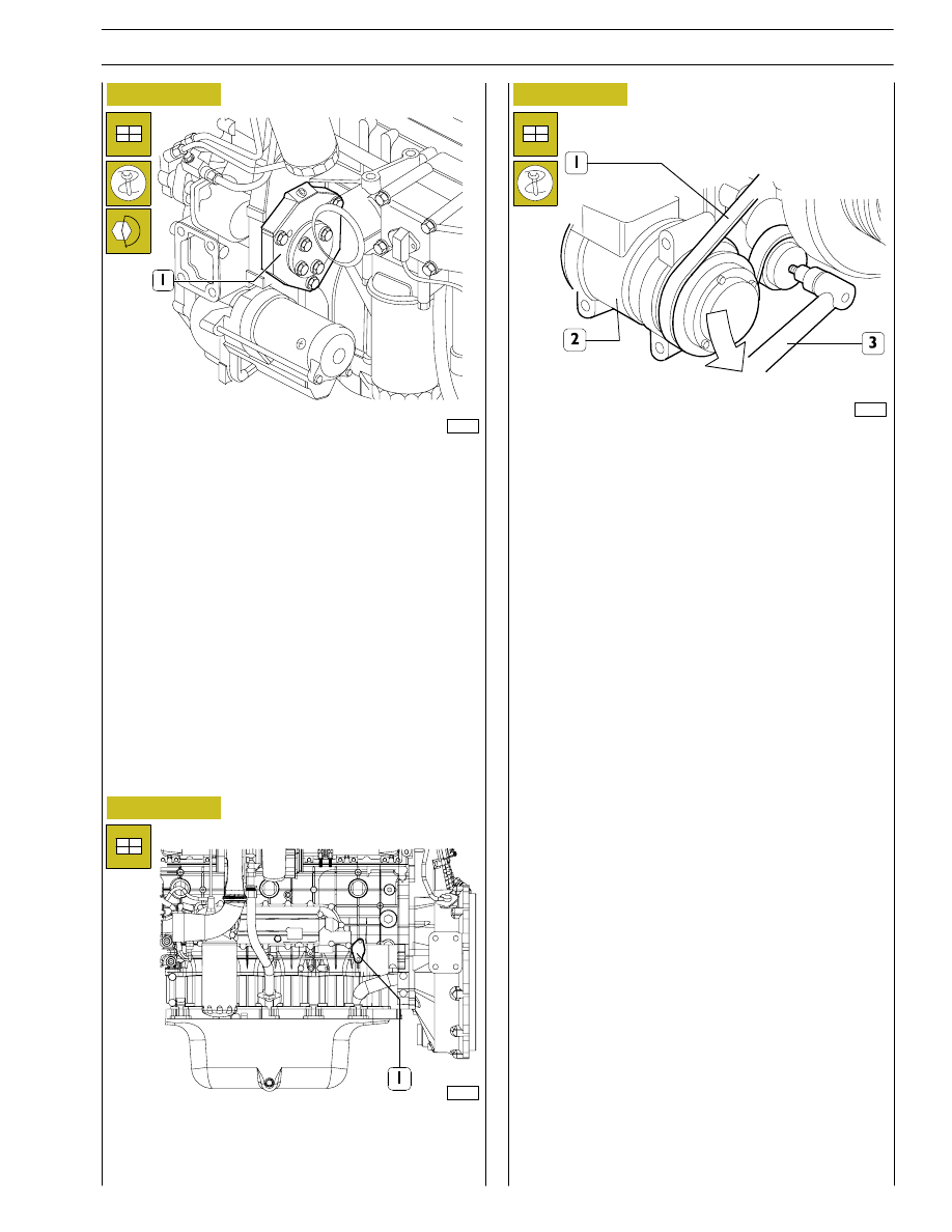
Figure 83
Figure 84
Figure 85
Fit the engine support together with the air-conditioner
compressor (2).
Using a suitable tool (3), work in the direction of the arrow and
mount the belt (1).
Connect the engine electric cable to the sensors and control
unit.
Refill the engine with lubricating oil of the prescribed grade and
quantity.
Fit the arm 99360585 onto the engine lifting hooks and hook
the arm onto the hoist.
Take out the screws fixing the brackets 99361036 to the
rotary stand. Lift the engine and remove the above-mentioned
brackets from it.
Complete engine assembly with the following parts, tightening
the fixing screws or nuts to the prescribed torque:
-
mount the drive (1);
-
mount the engine supports;
-
mount the oil pressure adjuster valve (1).
99254
99253
99357
SECTION 3 - INDUSTRIAL APPLICATION
27
Нет комментариевНе стесняйтесь поделиться с нами вашим ценным мнением.
Текст