Engine Iveco C10/C13/C78/Cursor 13/Cursor 78. Manual — part 29
47593
Figure 70
Figure 71
61831
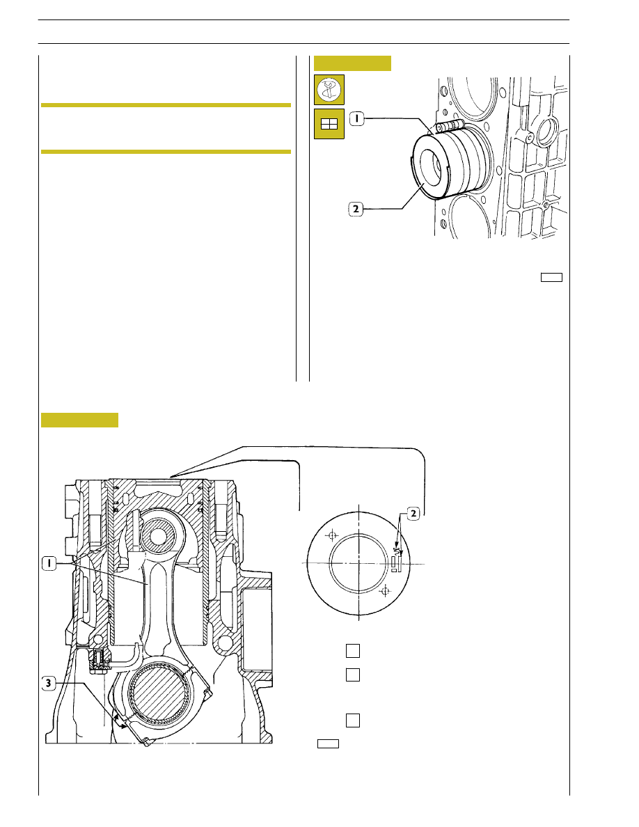
Connecting rod-piston assembly
Marking area on the piston crown of ideogram
specifying the assembly position and the
selection class
Connecting rod marking area (see Figure 61).
1
2
3
Fit the connecting rod-piston assemblies (1) into the piston
liners (2) using band 99360605 (1, Figure 71). Check the
following:
- the openings of the split rings are offset by 120
°;
- all pistons belong to the same class, A or B;
- ideogram stamped on the piston crown is placed toward
the engine flywheel, or the cavity, on the piston cover,
corresponds to the position of the oil spray nozzles.
As spares, class A pistons are provided and can be
fitted also to cylinder barrels belonging to class B.
Piston protrusion check
Once assembly is complete, check piston protrusion from
cylinder barrels: it must be 0.32-0.99 mm.
Fitting the connecting rod-piston assembly
into the piston liners
NOTE
34
SECTION 4 - OVERHAUL AND TECHNICAL SPECIFICATIONS
Install the connecting rod caps (1) with half-bearings; tighten
the connecting rod cap fixing screws (2) to 50 Nm (5 kgm)
torque. By tool 99395216 (3), tighten the screws further at
40
° angle.
Remove the caps and check the clearance by comparing the
width of the calibrated wire with the scale calibration on the
envelope containing the wire.
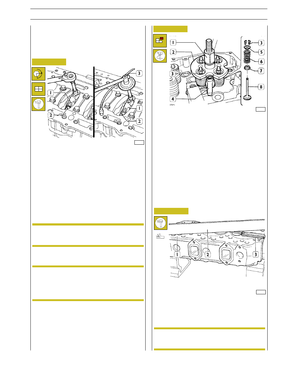
CYLINDER HEAD
Before dismounting cylinder head, check cylinder head for
hydraulic seal by proper tooling; in case of leaks not caused
by cup plugs or threaded plugs, replace cylinder head.
47594
47583
36159
Figure 72
Figure 73
Figure 74
Install and fix tool 99360264 (2) with bracket (4); tighten by
lever (1) until cotters are removed (3); remove the tool (2)
and the upper plate (5), the spring (6) and the lower plate (7).
Repeat the operation on all the valves. Turn the cylinder head
upside down and remove the valves (8).
The planarity (1) is checked using a ruler (2) and a thikness
gauge (3). If deformations exist, surface
the head using
proper surface grinder; the maximum amount of material to
be removed is 0.2 mm.
To check the clearance proceed as follows:
Connect the connecting rods to the relative main journals,
place a length of calibrated wire on the latter.
α
Checking the planarity of the head on the
cylinder block
(Demonstration)
After leveling, make sure that valve sinking and
injector protrusion are as described in the relative
paragraph.
Checking assembly clearance of big end pins
In case of plugs dismounting/replacement, on
mounting, apply sealant Loctite 243 IVECO nr.
2992693 on plugs.
NOTE
Dismounting the valves
Before dismounting cylinder head valves, number
them in view of their remounting in the position
observed on dismounting should they not have to
be overhauled or replaced.
NOTE
NOTE
SECTION 4 - OVERHAUL AND TECHNICAL SPECIFICATIONS
35
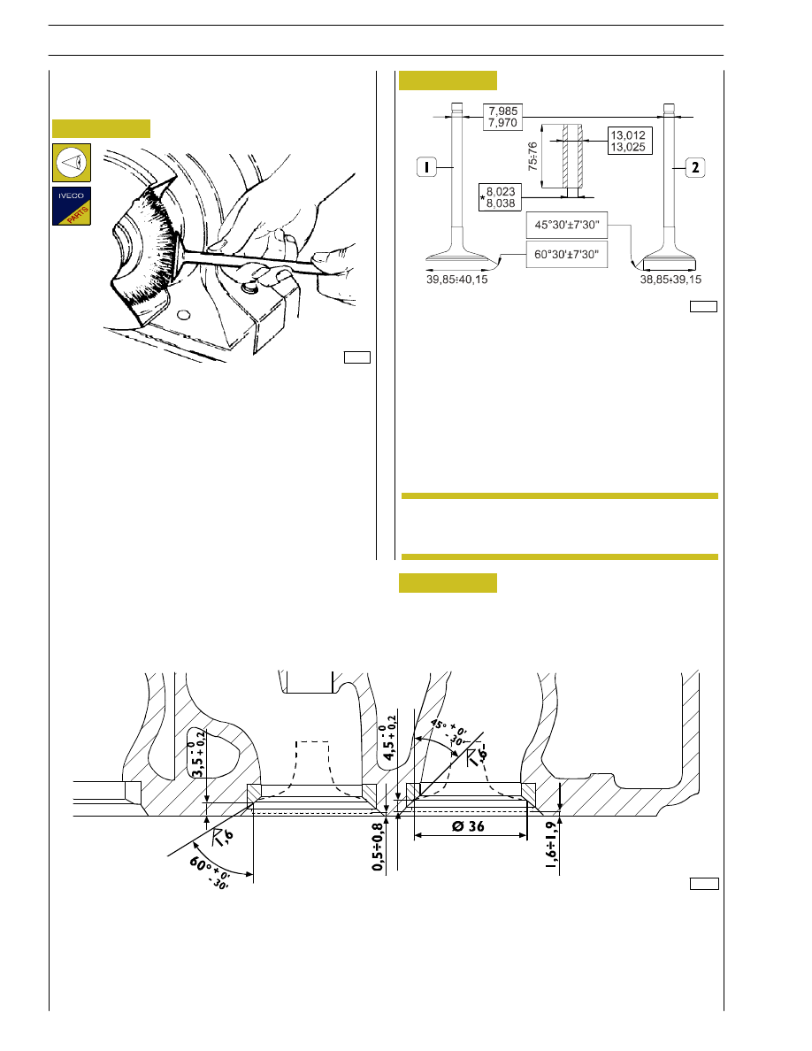
MAIN DATA - VALVES AND VALVE GUIDES
* Values to be obtained after installing the valve guides
99280
Figure 75
Figure 76
Check, by means of a micrometer, that valve stem diameters
are as specified; if necessary, grind the valves seat with a
grinder, removing the minimum quantity of material.
MAIN DATA OF VALVE SEATS
1. Intake valve seat — 2. Exhaust valve seat.
1) Inlet - 2) Exhaust
Figure 77
48625
VALVE
Removing deposits and checking the valves
Remove carbon deposits using the metal brush supplied.
Check that the valves show no signs of seizure or cracking.
Check the diameter of the valve stem using a micrometer
(see Figure 75) and replace if necessary.
Valve seats
Regrinding — replacing valve seats
The valve seats are reground whenever the valves
or valve guides are ground and replaced.
NOTE
108307
36
SECTION 4 - OVERHAUL AND TECHNICAL SPECIFICATIONS
41032
45634
Figure 78
Figure 79
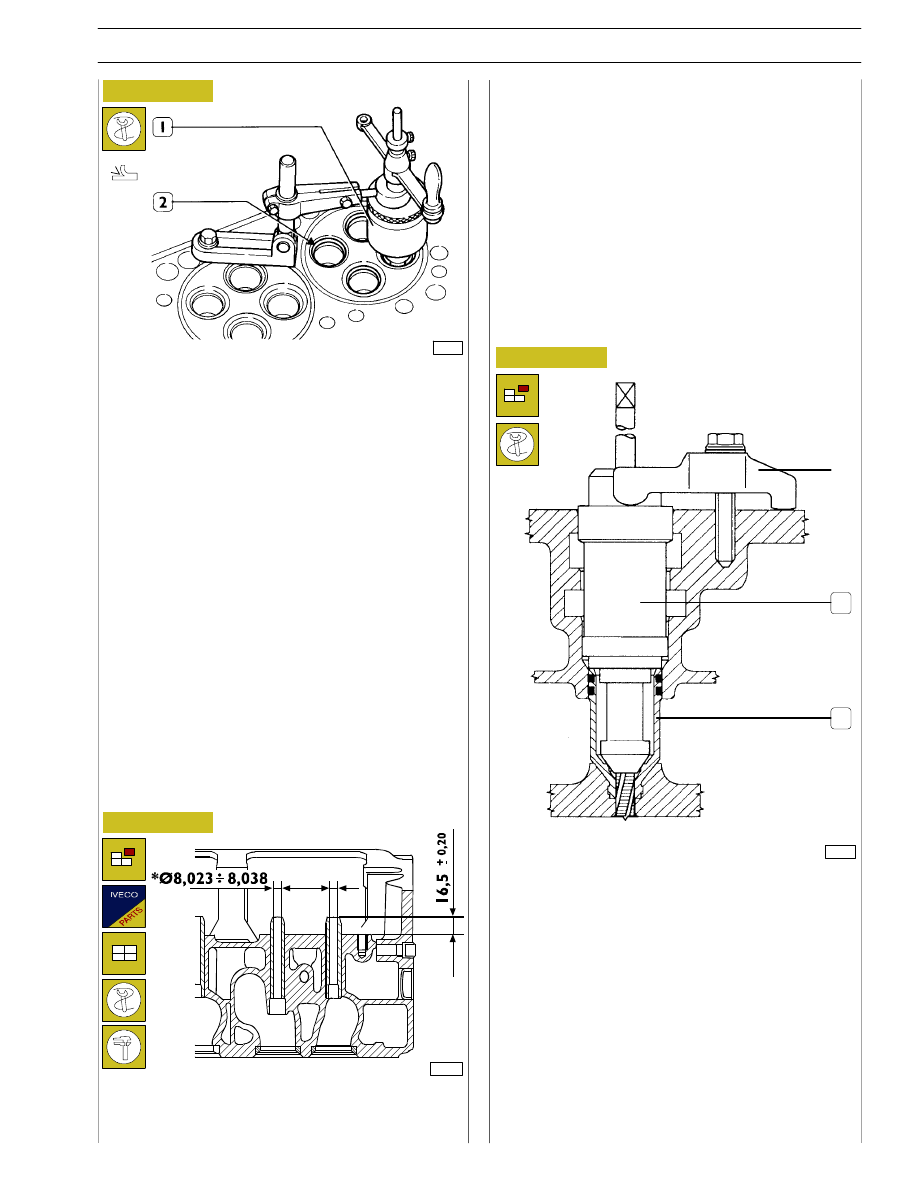
To replace the injector case (2), act as follows:
- thread the case (2) with tool 99390804 (1).
Carry out operations described in figs. 80 - 83 - 84 - 85 by
fixing tools to the cylinder head by means of braket A.
REPLACING INJECTOR HOLDER CASES
Removal
1
2
A
Check the valve seats (2). If you find any slight scoring or
burns, regrind them with tool 99305019 (1) according to the
angles shown in Figure 78. If it is necessary to replace them,
using the same tool and taking care not to affect the cylinder
head, remove as much material as possible from the valve
seats so that, with a punch, it is possible to extract them from
the cylinder head.
Heat the cylinder head to 80
÷ 100°C and, using a drift, fit
in the new valve seats (2), chilled beforehand in liquid
nitrogen. Using tool 99305019 (1), regrind the valve seats
according to the angles shown in Figure 77.
After regrinding the valve seats, using tool 99370415 and dial
gauge 99395603, check that the position of the valves in
relation to the plane of the cylinder head is:
- -0.5
÷ -0.8 mm (recessing) intake valves
- -1.6
÷ -1.9 mm (recessing) exhaust valves.
Checking clearance between valve-stem and
associated valve guide
Using a dial gauge with a magnetic base, check the clearance
between the valve stem and the associated guide. If the
clearance is too great, change the valve and, if necessary, the
valve guide.
Valve guides
Replacing valve guides
Figure 80
The valve guides are removed with the drift 99360143.
They are fitted with the drift 99360143 equipped with part
99360296.
108308
Part 99360296 determines the exact position of assembly of
the valve guides in the cylinder head. If they are not available,
you need to drive the valve guides into the cylinder head so
they protrude by 16.3
÷16.7 mm (Figure 79).
After driving in the valve guides, rebore their holes with the
smoother 99390330.
SECTION 4 - OVERHAUL AND TECHNICAL SPECIFICATIONS
37
Нет комментариевНе стесняйтесь поделиться с нами вашим ценным мнением.
Текст