Loader Bobcat 853, 853H. Manual — part 66
VALVES, VALVE SEAT AND GUIDE
Removal
The tools listed will be needed to do the following
procedure:
MEL1266 – Valve Stem Seal Installer
Mark the valves and parts so they are returned to their
original position when assembling.
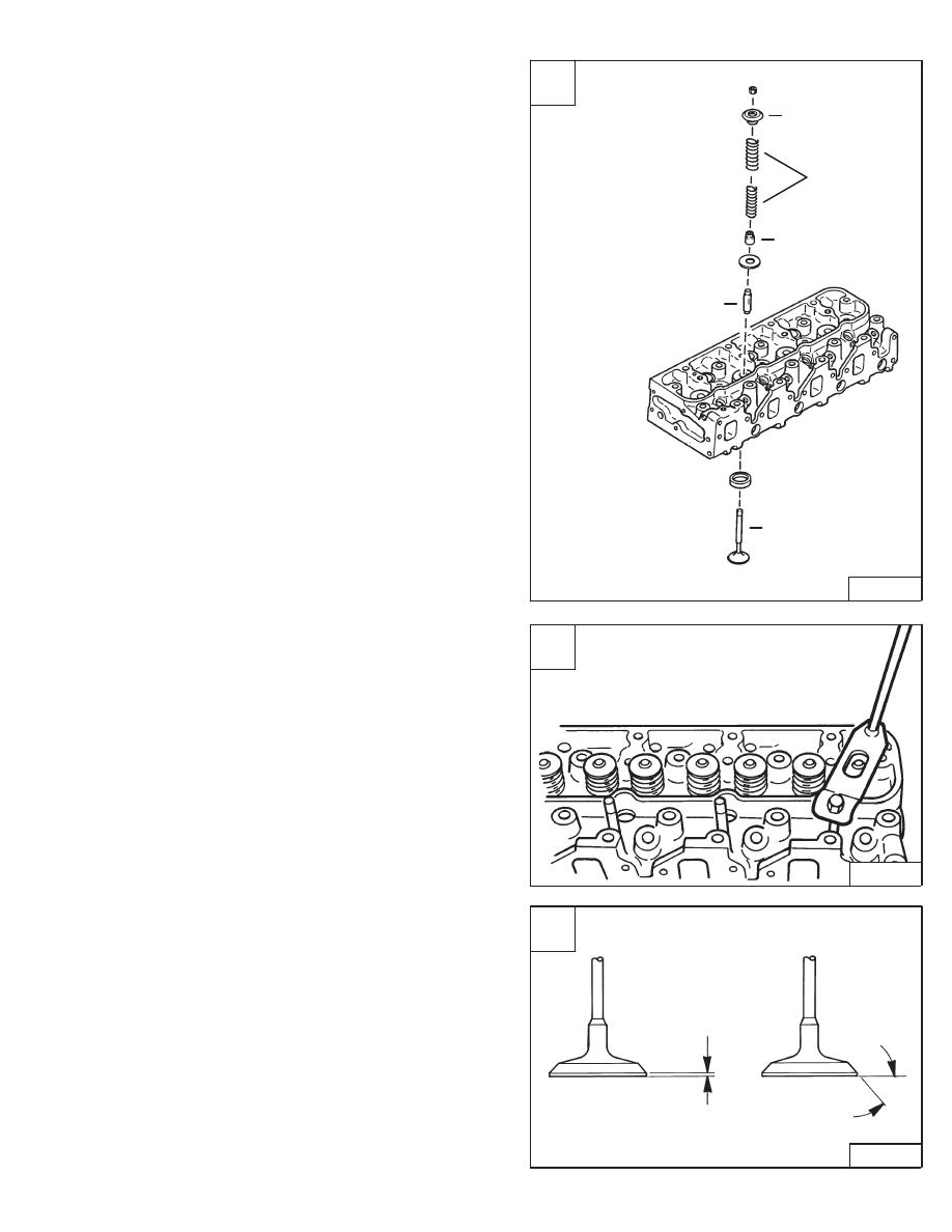
Remove the valve spring locks [A], using a spring
compressor [B].
Remove the valve springs, spring seats, oil seal and valve
[A].
Before reassembly, check the valves, valve seats and
guides.
Installation
Make sure the head is clean.
Put oil on the valve guides and valve stems.
Put each valve in the correct location.
Install the valve springs, spring seats and oil seals [A].
NOTE: Install the valve springs with their closed
pitched (painted side) end toward the
cylinder head.
Use a valve spring compressor and install the valve
spring locks.
Tap the valve stem with a hammer a small amount to seat
the valve stem locks.
Reconditioning The Valve And Valve Seats
Use the correct equipment to grind the valve and valve
seats.
The angle of the intake and exhaust valves is 45
°
[C].
The valve head thickness is as listed [C]:
Standard – 0.071 inch (1,8 mm)
Limit – 0.059 inch (1,5 mm)
B
B–08193
C
B–08202
Thickness
45
°
A
B–08192
1.
Spring Seat
2.
Springs
3.
Valve
4.
Oil Seal
5.
Spring Seat
1
5
4
4
2
853, 853H Loader
–7–53–
Service Manual
VALVES, VALVE SEAT AND GUIDE (Cont’d)
Reconditioning The Valve And Valve Seats (Cont’d)
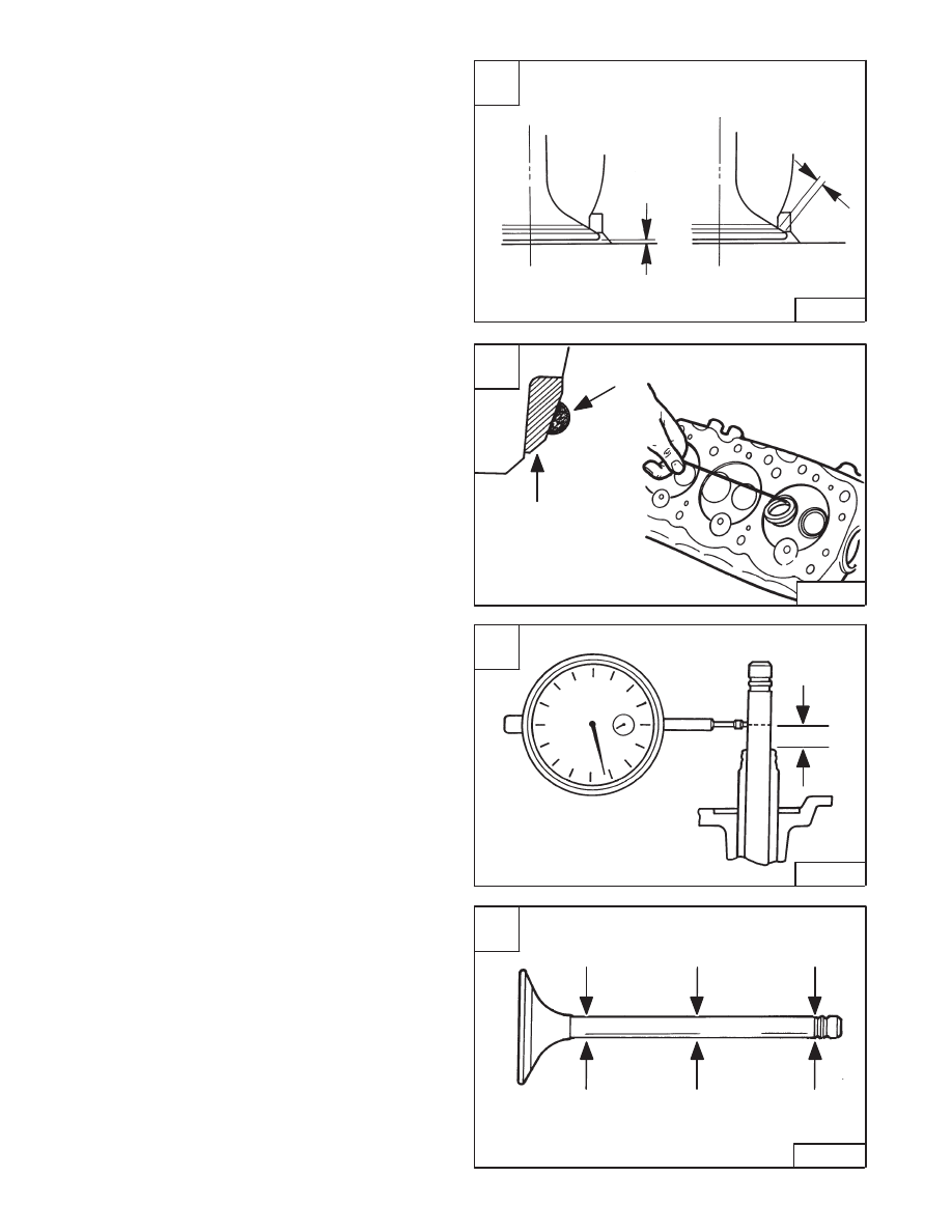
Check the valve head depth in the cylinder head after
grinding the valves and seat. The correct specifications
are as follows[A]:
Intake –
Standard
0.029 inch (0,74 mm)
Limit
0.05 inch (1,27 mm)
Exhaust – Standard
0.028 inch (0,71 mm)
Limit
0.047 inch (1,20 mm
Check the valve seat contact width [A]:
Intake –
Standard
0.067 inch (1,70 mm)
Limit
0.087 inch (2,21 mm)
Exhaust – Standard
0.079 inch (2,0 mm)
Limit
0.098 inch (2,48 mm)
Valve Seat Insert
To remove the valve seat insert, put a bead of weld around
the inner face of the insert and allow to cool a few minutes,
then pry them out [B].
Press the new valve seat insert into the bore using a
hydraulic press.
After installation, grind the insert to the correct angle and
check the depth of the valve.
Valve Guide
The tools listed will be needed to do the following
procedure:
MEL1259 – Valve Guide Remover
Check the valve guides for wear with a dial indicator [C].
If the movement is more than the listed specifications,
replace the guide.
Intake –
Standard
0.0015–0.0027 inch
(0,038–0,069 mm)
Limit
0.008 inch (0,2 mm)
Exhaust – Standard
0.0025–0.0038 inch
(0,064–0,96 mm)
Limit
0.010 inch (0,25 mm)
NOTE: Check the valve stem for wear before
replacing the valve guide [D].
A
B–08199
Depression
Contact
Width
C
B–08205
0.40 ”
(10 mm)
D
B–08204
Intake
Standard
0.3128–0.3134 ”
(7,946–7,961 mm)
Exhaust
Standard
0.3119–0.3124 ”
(7,921–7,936 mm)
Limit
0.310 ”
(7,88 mm)
–7–54–
853, 853H Loader
Service Manual
B
B–08201
Welding
Bead
Valve Seat
Insert
VALVES, VALVE SEAT AND GUIDE (Cont’d)
Valve Guide (Cont’d)
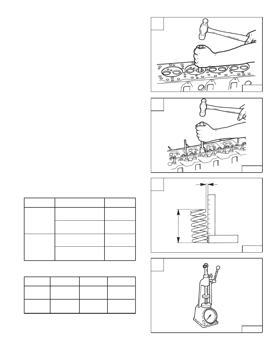
Remove the guide [A].
Install the new guide [B].
The height of the valve guide top edge to the cylinder is
0.51 inch. (13,0 mm).
Valve Spring
Check the free length and inclination [C].
Std.
Limit
Inner
1.783 inch
1.748 inch
(45,3 mm)
(44,4 mm)
Free Length
Outer
1.957 inch
1.898 inch
(49,7 mm)
(48,2 mm)
Inner
–––
0.118 inch
(3,0 mm)
Inclination
Outer
–––
0.126 inch
(3,2 mm)
Check the valve spring tension [D].
Set Length
Std.
Limit
Inner
1.46 inch
13 lbs.
11 lbs.
(37,0 mm)
(5,9 kg)
(5,02 kg)
Outer
1.54 inch
46 lbs.
40 lbs.
(39,1 mm)
(20,9 kg)
(18,1 kg)
A
B–08206
C
B–08208
Square
Inclination
Free Length
D
B–08209
853, 853H Loader
–7–55–
Service Manual
B
B–08207
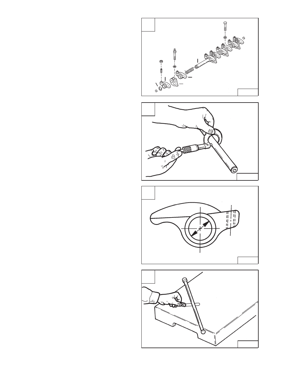
ROCKER ARM AND SHAFT
Disassembly And Assembly
Mark the rocker arms and support brackets for correct
assembly.
Remove the snap ring (Item 1) [A] from each end of the
shaft (Item 5) [A].
Remove the rocker arms (Items 2 & 4) and support
brackets (Item 3) [A].
Assembly: The support bracket with the oil hole is toward
the front of the engine.
Inspect all the parts for wear or damage.
Check the rocker arm O.D. [B].
Standard – 0.7478–0.7486 inch (18,98–19,0 mm)
Limit – 0.7427 inch (18,85 mm)
Checking Rocker Arm And Push Rods
Check the rocker arm [C].
Rocker arm diameter.
Standard – 0.7489–0.7497 inch (19,01–19,03 mm)
Limit – 0.7505 inch (19,05 mm)
Clearance between rocker arm and shaft.
Standard – 0.0003–0.002 inch (0,008–0,051 mm)
Limit – 0.0078 inch (0,20 mm)
Replace the parts as needed.
Check the push rods for run–out [D].
Limit – 0.012 inch (0,3 mm)
A
B–08191
5
4
3
2
1
C
B–08215
D
B–08213
–7–56–
853, 853H Loader
Service Manual
B
B–08214
Нет комментариевНе стесняйтесь поделиться с нами вашим ценным мнением.
Текст