Loader Bobcat 773. Manual — part 26

CONTROL VALVE (S/N 509640660 & Above, S/N
509616542 & Above) (Cont’d)
Lift Spool And Detent (Cont’d)
Assembly (Cont’d)
Install the washer (Item 1) [A], spring (Item 2) [A] and
collar/detent adapter assembly (Item 3) [A].
Tighten the detent adapter (Item 1) [B] to 90–100 in.–lbs.
(10,2–11,3 Nm) torque.
Install the detent sleeve (Item 1) [C], detent balls and
spring in the detent adapter (Item 2) [C] using the detent
installation tool (MEL1278).
Install the lift spool assembly in the spool bore [D].
A
P–08989
3
2
1
C
P–11011
1
2
D
P–11012
–2–50–
773 BICS Loader
Service Manual
773 Service Manual #6900092–Hydraulic System Section Part 2 of 4
B
P–08988
1

CONTROL VALVE (S/N 509640660 & Above, S/N
509616542 & Above) (Cont’d)
Lift Spool And Detent (Cont’d)
Assembly (Cont’d)
Install the detent bonnet (Item 1) [A] and two bolts (Item
2) [A].
Tighten the bolts to 90–100 in.–lbs. (10,2–11,3 Nm)
torque.
Install the washer (Item 1) [B] and snap ring (Item 2) [B].
Rubber Boot
Assembly
Install the O–ring (Item 1) [C] and bushing (Item 2) [C].
Install the rubber boot (Item 1) [D] and retainer (Item 2)
[D].
NOTE: Make sure the rubber boot sits in the sealing
surface of the spool.
Revised June 01
A
P–08983
2
1
2
C
P–08981
1
2
D
P–08980
1
2
773 BICS Loader
–2–51–
Service Manual
B
P–08982
1
2

CONTROL VALVE (S/N 509640660 & Above, S/N
509616542 & Above) (Cont’d)
Rubber Boot (Cont’d)
Assembly (Cont’d)
Install the two bolts (Item 1) [A].
Tighten the bolts to 90–100 in.–lbs. (10,2–11,3 Nm)
torque.
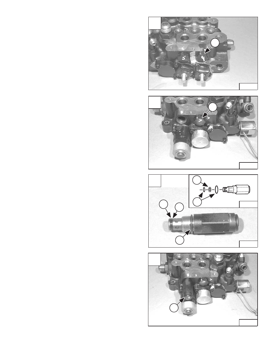
Anti–Cavitation Valve
Assembly
Install new O–rings (Item 1) [B] and back–up ring (Item
2) [B] on the plug.
Install the plug (Item 1) [C] in the tilt section of the control
valve.
Tighten to 35–40 ft.–lbs. (47–54 Nm) torque.
NOTE: On later models only this port may contain an
available 3500 PSI port relief valve for the rod
end of the tilt section
Install new O–rings (Item 1) [D] and back–up ring (Item
2) [D] on both anti–cavitation valves.
Revised May 98
A
P–08979
1
1
C
P–08977
1
D
P–08976
2
1
E–01509
1
2
–2–52–
773 BICS Loader
Service Manual
B
P–08978
2
1
E–01509
2
1
CONTROL VALVE (S/N 509640660 & Above, S/N
509616542 & Above) (Cont’d)
Anti–Cavitation Valve (Cont’d)
Assembly (Cont’d)
Install the anti–cavitation valve (Item 1) [A] on the control
valve lift section.
Tighten to 35–40 ft.–lbs. (47–54 Nm) torque.
Install the anti–cavitation valve (Item 1) [B] on the control
valve tilt section.
Tighten to 35–40 ft.–lbs. (47–54 Nm) torque.
Port Relief Valve
Assembly
Install new O–rings (Item 1) [C] and back–up ring (Item
2) [C] on the port relief valve.
Install the port relief valve (Item 1) [D].
Tighten to 35–40 ft.–lbs. (47–54 Nm) torque.
NOTE: This port may contain an available 3500 PSI
anti–cavitation/port relief valve for the base
end of the tilt section.
Revised May 98
A
P–08975
1
C
P–08973
E–01509
1
1
2
2
1
D
P–08972
1
773 BICS Loader
–2–53–
Service Manual
B
P–08974
1
Нет комментариевНе стесняйтесь поделиться с нами вашим ценным мнением.
Текст