Loader Bobcat 773. Manual — part 25
CONTROL VALVE (S/N 509640660 & Above, S/N
509616542 & Above) (Cont’d)
Auxiliary Electric Solenoid (Cont’d)
Assembly (Cont’d)
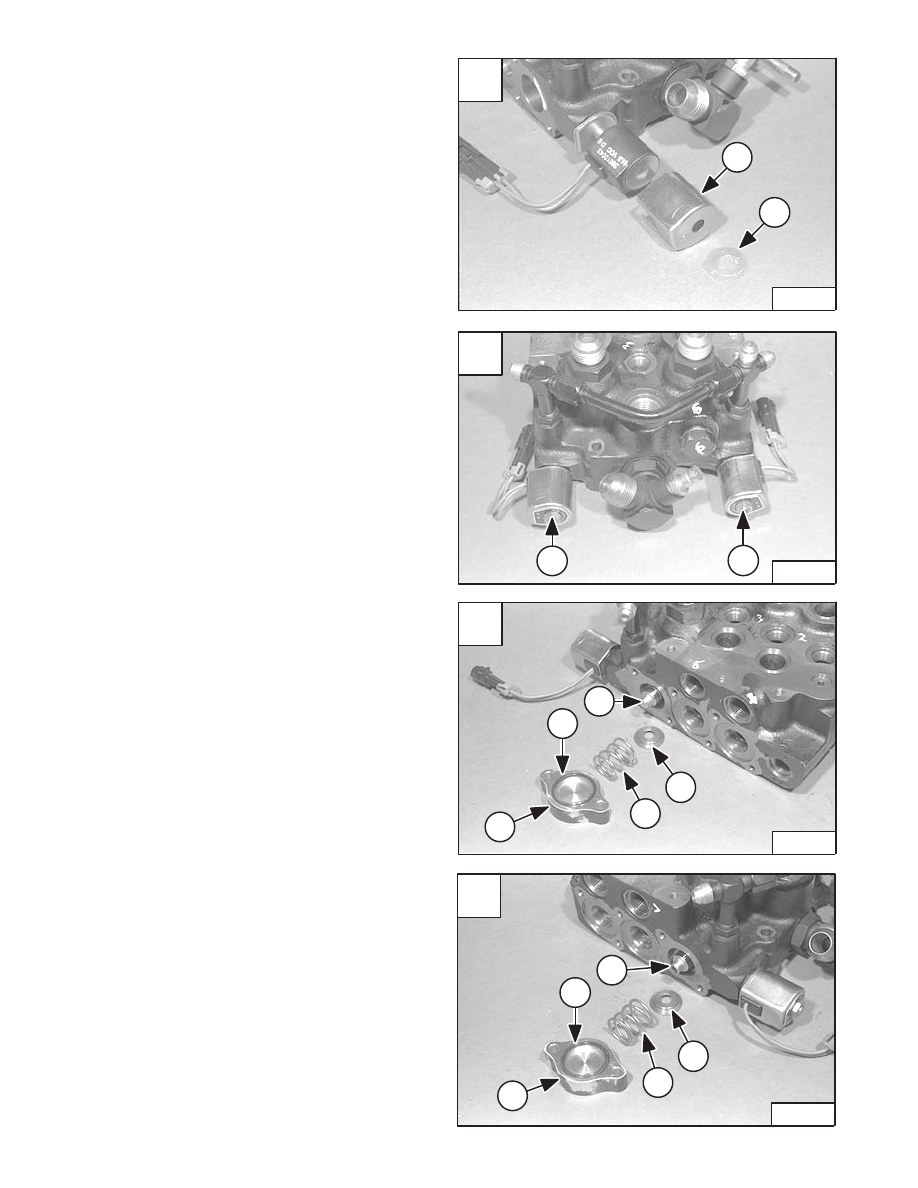
Install the housing (Item 1) [A] and the end plate (Item 2)
[A].
Install the nut (Item 1) [B] on the solenoid valve.
Tighten the nut to 9–12 in.–lbs. (1,02–1,36 Nm) torque.
Auxiliary Spool
Assembly
Install the auxiliary spool (Item 1) [C] & [D] in the control
valve.
Install the spring seats (Item 2) [C] & [D] and springs
(Item 3) [C] & [D].
Install the O–rings (Item 4) [C] & [D] in the spool covers
(Item 5) [C] & [D].
A
P–11005
1
2
C
P–11002
2
3
5
4
1
D
P–11003
2
3
5
4
1
–2–46–
773 BICS Loader
Service Manual
B
P–11004
1
1
CONTROL VALVE (S/N 509640660 & Above, S/N
509616542 & Above) (Cont’d)
Auxiliary Spool (Cont’d)
Assembly (Cont’d)
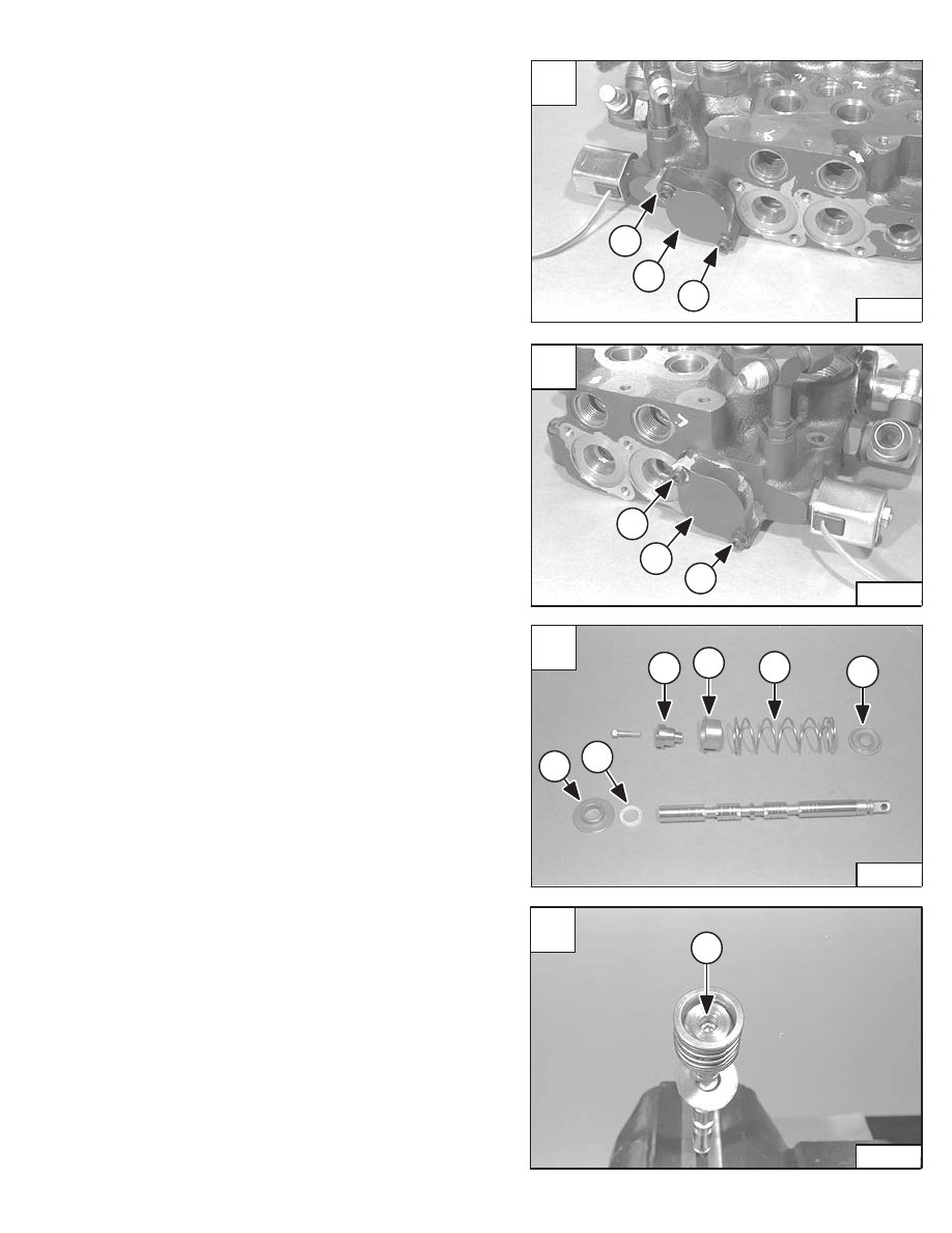
Install the auxiliary spool covers (Item 1) [A] & [B].
Install the two bolts (Item 2) [A] & [B].
Tighten the bolts to 90–100 in.–lbs. (10,2–11,3 Nm)
torque.
Tilt Spool And Centering Spring
Assembly
Slide a new spool seal (Item 1) [C] on the spool.
NOTE: The spool seal must be installed with the lip
face toward the valve body. The lip face has
the largest outside diameter.
Install the bushing (Item 2) [C], washer (Item 3) [C],
spring (Item 4) [C], collar (Item 5) [C], and adapter (Item
6) [C].
Clamp the activating end of the tilt spool in a vise.
Install the centering spring bolt (Item 1) [D].
Tighten the bolt to 90–100 in.–lbs. (10,2–11,3 Nm) torque.
A
P–11000
2
2
1
C
P–08999
6
5
4
3
1
2
D
P–08998
1
773 BICS Loader
–2–47–
Service Manual
B
P–11001
2
2
1
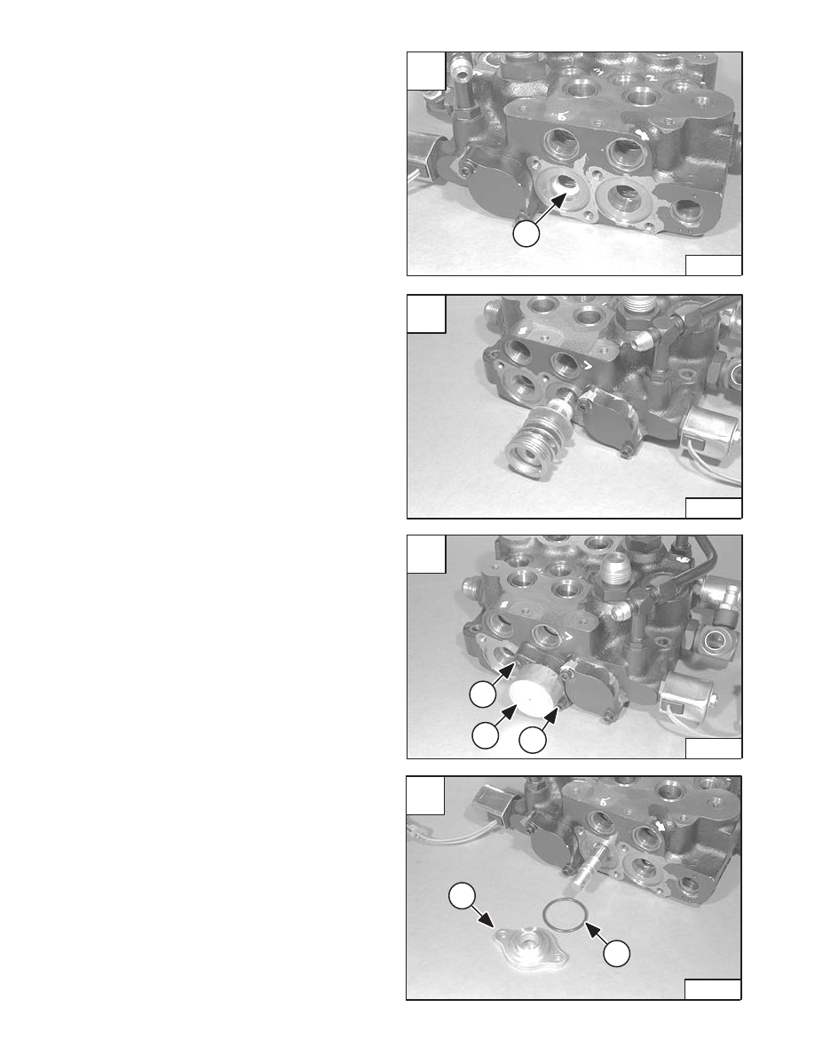
Install the spool assembly [B].
Install the end cap (Item 1) [C] and the two retaining bolts
(Item 2) [C].
Tighten the bolts to 90–100 in.–lbs. (10,2–11,3 Nm)
torque.
Install the O–ring (Item 1) [D] on the bushing (Item 2) [D].
Install the bushing (Item 2) [D] over the actuating end of
the tilt spool.
CONTROL VALVE (S/N 509640660 & Above, S/N
509616542 & Above) (Cont’d)
Tilt Spool And Centering Spring (Cont’d)
Assembly (Cont’d)
Install the spool seal (Item 1) [A] in the spool bore.
NOTE: The spool seal must be installed with the lip
face toward the valve body. The lip face has
the largest outside diameter.
A
P–08997
1
C
P–08995
2
1
2
D
P–08994
2
1
–2–48–
773 BICS Loader
Service Manual
B
P–08996
CONTROL VALVE (S/N 509640660 & Above, S/N
509616542 & Above) (Cont’d)
Tilt Spool And Centering Spring (Cont’d)
Assembly (Cont’d)
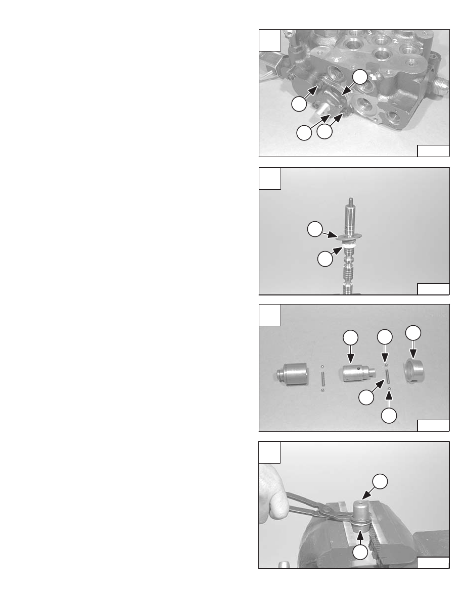
Install the rubber boot (Item 1) [A] and retainer (Item 2)
[A] over the actuating end of the tilt spool.
NOTE: Make sure the rubber boot sits in the sealing
surface of the spool.
Install the two bolts (Item 3) [A] on the rubber boot
retainer.
Tighten the bolts to 90–100 in.–lbs. (10,2–11,3 Nm)
torque.
Lift Spool And Detent
Assembly
Clamp the actuating end of the lift spool in a vise.
Install the spool seal (Item 1) [B] and bushing (Item 2) [B].
Apply grease on all the detent component surfaces before
assembly [C].
Install the detent adapter (Item 1) [C] & [D], detent balls
(Item 2) [C] and spring (Item 3) [C] in the collar (Item 4)
[C] & [D] using the detent installation tool (MEL1278).
A
P–08992
3
3
2
1
C
P–11009
1
4
2
2
3
D
P–11010
1
4
773 BICS Loader
–2–49–
Service Manual
B
P–08990
1
2
Нет комментариевНе стесняйтесь поделиться с нами вашим ценным мнением.
Текст