Loader Bobcat 773. Manual — part 102
A
P–04705
2
1
N–00960
SEAT SENSOR (Cont’d)
BICS
™
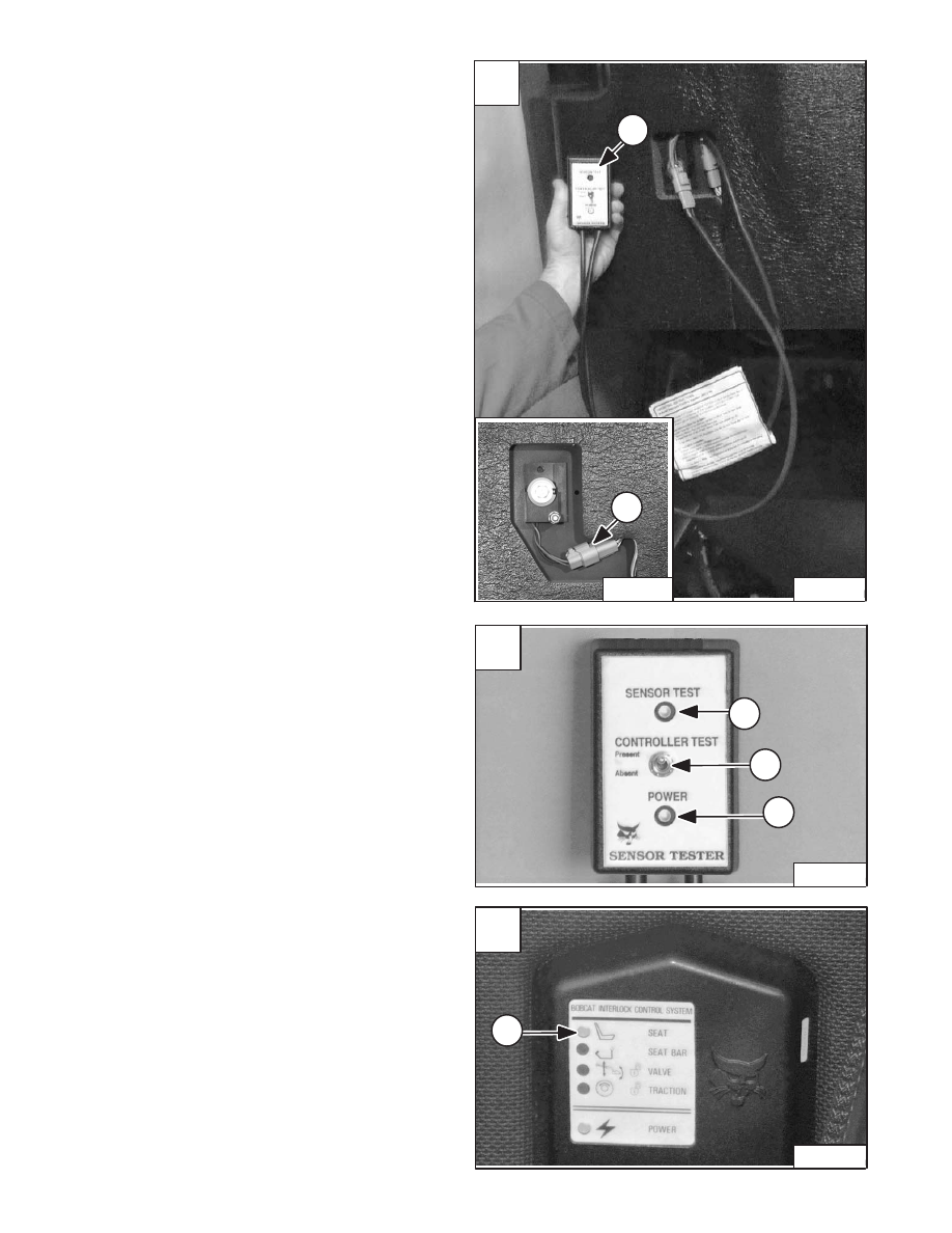
Controller Seat Sensor Circuit Test
Use Sensor Tester (MEL1428) for the following
procedure:
Disconnect the short adatper test leads if connected.
Revised Jan. 99
Turn the key to the ON position. DO NOT START THE
ENGINE.
The power light (Item 1) [B] will illuminate, if the light is not
on, check the tester or wiring harenss.
Move the toggle switch (Item 2) [B] on the sensor tester
to the Present position.
Raise the operator cab. (See Page 1–1.)
Disconnect the seat sensor connector (Item 1 – Inset)
[A].
Connect MEL1428 Sensor Tester (Item 2) [A] inline as
shown to the seat sensor.
Lower the operator cab. (See Page 1–1.)
NOTE: Clean any debris, dirt or objects from under
or behind the operator seat before starting
the test. The rear of the seat must move up
and down.
The Seat light (Item 1) [C] on the controller will illuminate.
Move the toggle switch to Absent position, the seat light
on the controller will go off.
If the tests above fail, there is a problem with the BICS
system controller or the wiring harness.
NOTE: The sensor test light (Item 3) [B] is activated
by the seat sensor switch.
B
P–04703
2
1
3
–8–14–
773 BICS Loader
Service Manual
C
P–04706
1
BICS
™
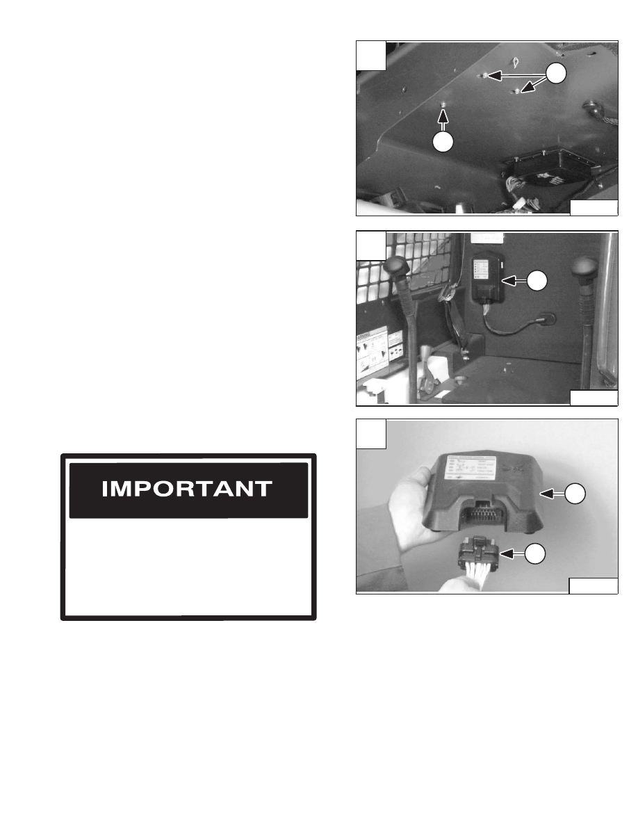
SYSTEM CONTROLLER
Removal And Installation
NOTE: The operator seat is removed in photo [B] for
clarity purpose only. The seat does not need
to be removed to remove the controller.
Slide the controller (Item 1) [B] up and remove it from the
back of the operator cab.
Disconnect the electrical harness from the controller and
remove the controller from the loader.
Installation: Tighten the controller mounting bolts to
80–90 in.–lbs. (9–10 Nm) torque.
Reverse the removal procedure to install the controller.
NOTE: Install the harness connector (Item 1) [C] into
the controller (Item 2) [C] before installing the
controller.
Raise the operator cab. (See Page 1–1.)
The controller mounting bolts are located on the back of
the operator cab [A].
Remove the top mounting bolt (Item 1) [A] from the
controller.
Loosen the two lower mounting bolts (Item 2) [A].
Lower the operator cab.
NOTE: Photo’s may be different but the procedure is
the same for all models.
Be sure the connector to the BICS system
controller are correctly engaged in the
controller when installing the controller. An
audible snap can be heard when the
connector is correctly installed. Try to pull the
connector out of the controller, if it cannot be
removed it has been correctly installed [C].
I–2087–1095
Revised Jan. 99
A
P–03997
2
1
C
P–04707
2
1
773 BICS Loader
–8–15–
Service Manual
B
P–03994
1
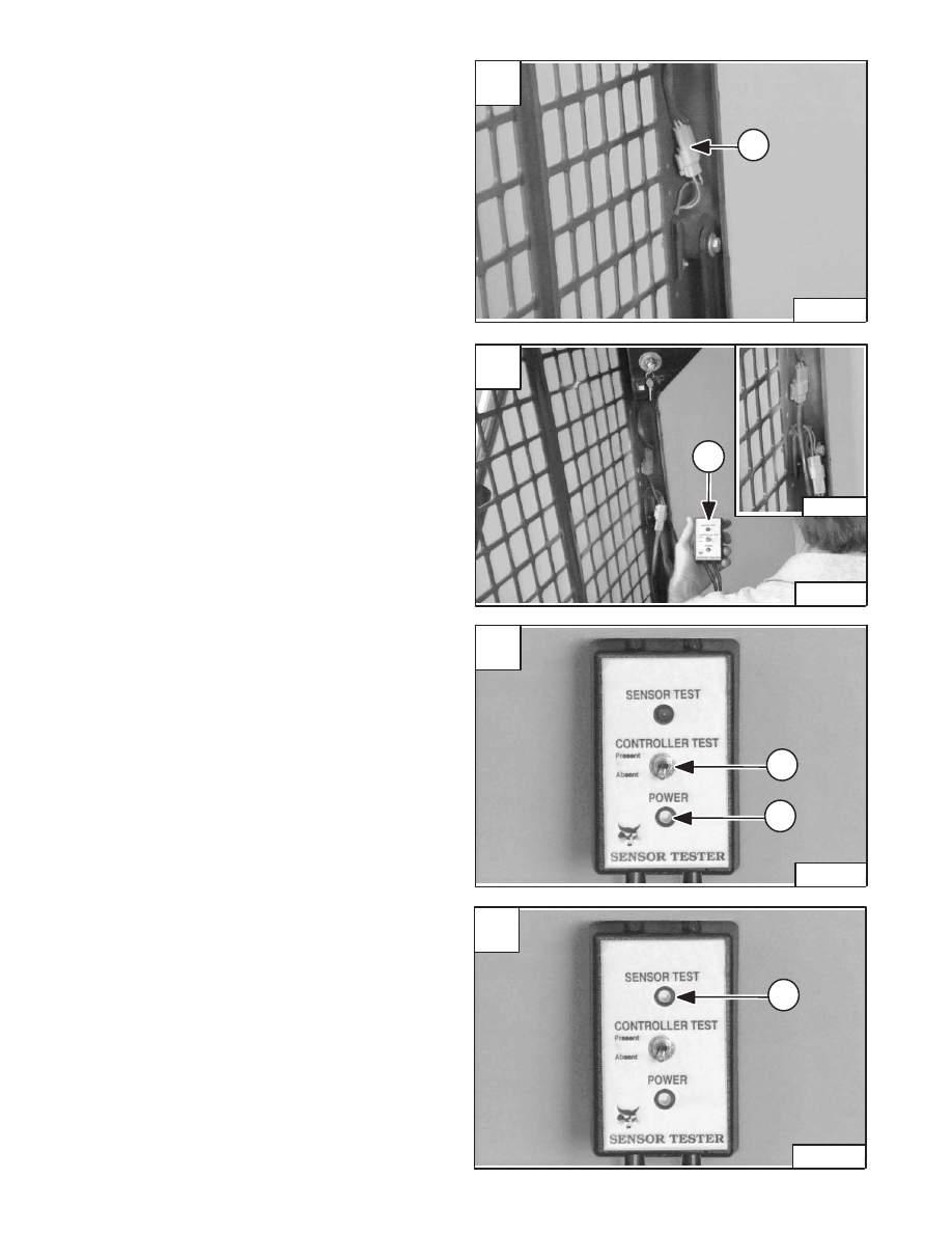
SEAT BAR SENSOR
Seat Bar Sensor Test
Use Sensor Tester (MEL1428) for the following
procedure:
Disconnect the short adatper test leads if connected.
Disconnect the seat bar sensor connector (Item 1) [A].
Connect Sensor Tester (Item 1) [B] inline as shown to the
seat bar sensor connectors. See inset [B].
Turn the key to the ON position. DO NOT START THE
ENGINE.
The toggle switch (Item 2) [C] can be in either the Absent
or Present position.
The power light (Item 1) [C] will illuminate, if the light is not
on, check the tester or wiring harness.
Lower the seat bar. The Sensor Test light (Item 1) [D]
should illuminate.
Raise the seat bar. The Sensor Test light (Item 1) [D]
should go off.
If the above tests fail, there is a problem with the seat bar
sensor.
Disconnect the Sensor Tester.
Replace the Seat Bar Sensor. (See Page 8–17.)
If the above tests pass, run BICS controller seat bar
circuit test. (See Page 8–18.)
Revised Jan. 99
A
P–04702
1
C
P–04698
1
2
D
P–04699
1
–8–16–
773 BICS Loader
Service Manual
B
P–04700
P–04701
1
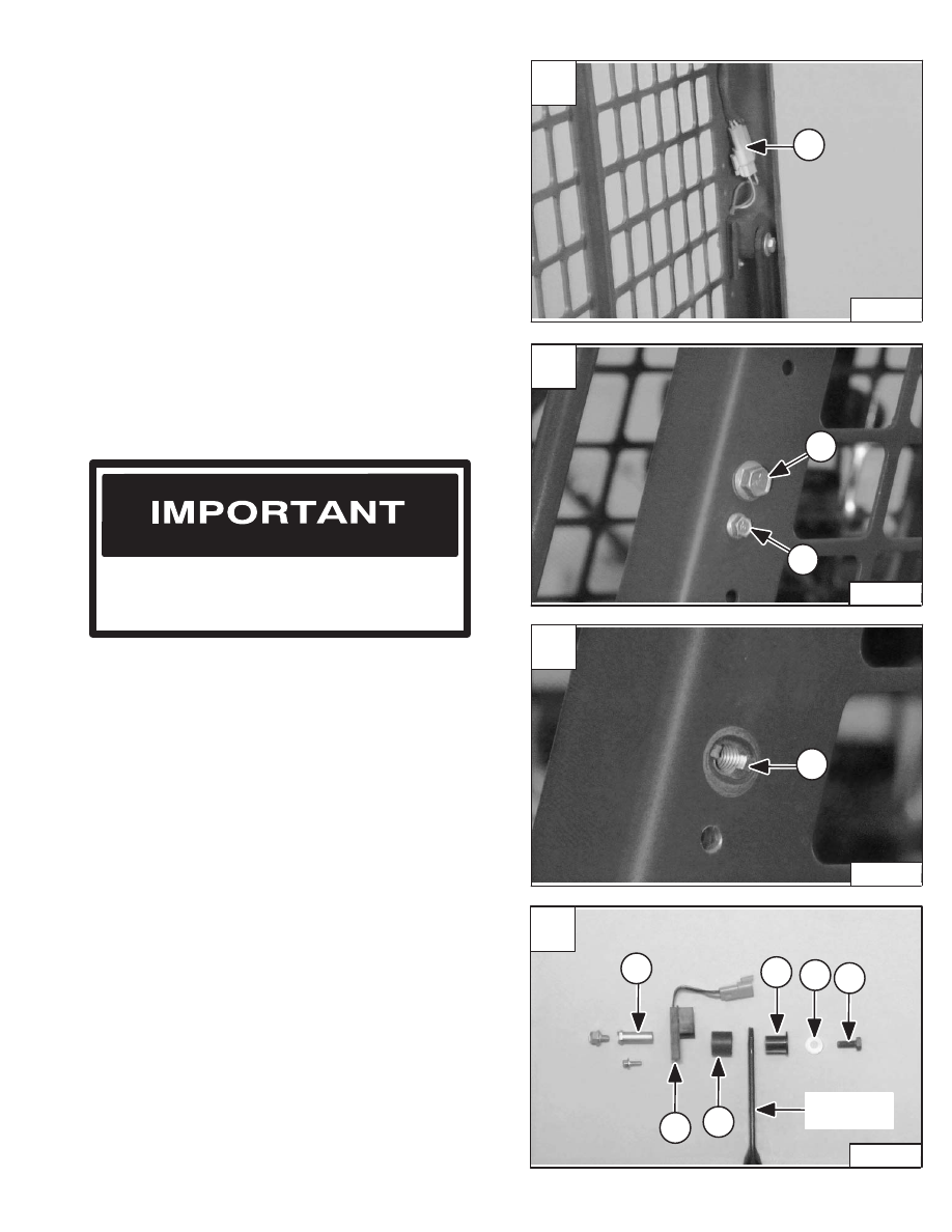
SEAT BAR SENSOR (Cont’d)
Removal And Installation
Disconnect the seat bar sensor connector (Item 1) [A].
Remove the mounting bolt (Item 1) [B] from the pivot
bushing.
Installation: Tighten the mounting bolt to 25–28 ft.–lbs.
(34–38 Nm) torque.
Remove the sensor mounting bolt (Item 2) [B] and nut.
NOTE: The sensor assembly [D] is shown removed
from the operator cab for clarity purpose
only. The sensor assembly can be removed
without removing the seat bar from the
operator cab.
Remove the pivot bushing mounting bolt (Item 1) [D] and
washer (Item 2) [D] from the pivot bushing (Item 3) [D].
Installation: Tighten the pivot bushing mounting bolt to
180–200 in.–lbs. (21–23 Nm) torque.
Remove the pivot bushing (Item 3) [D], sensor (Item 4)
[D], magnet (Item 5) [D] and plastic bushing (Item 6) [D]
from the seat bar.
Inspect all parts for damage and wear and replace if
necessary.
Reverse the removal procedure to install the seat bar
sensor.
Installation: Be sure the tabs on the pivot bushing are
positioned in the slotted hole (Item 1) [C] of the operator
cab as shown.
Pull the seat bar back and remove the assembly as
follows:
Be careful to not overtighten the sensor
mounting bolt and nut to prevent breakage of
the sensor.
I–2088–1095
Revised Jan. 99
A
P–04702
1
C
P–03247
1
D
P–03284
3
6
2
1
4
5
Left Side
of Seat Bar
773 BICS Loader
–8–17–
Service Manual
B
P–03246
1
2
Нет комментариевНе стесняйтесь поделиться с нами вашим ценным мнением.
Текст