DAF 95XF. Manual — part 241
5
Contents
CONNECTING ACCESSORIES
1
CONTENTS
Page
Date
1.
CONNECTING ACCESSORIES
1-1
0009
. . . . . . . . . . . . . . . . . . . . . . . . . . . . . . . . . . . . . . . . . .
. . . . . .
1.1
Connection points on printed circuit
1-1
0009
. . . . . . . . . . . . . . . . . . . . . . . . . . . . . . . . .
. . . . . .
1.2
Connecting accessories with a current consumption of 15 to 25 Amp
1-2
0009
. . . .
. . . . . .
1.3
Connecting accessories via the accessory connector
1-3
0009
. . . . . . . . . . . . . . . . . .
. . . . . .
1.4
Overview of connection points in roof console
1-4
0009
. . . . . . . . . . . . . . . . . . . . . . . .
. . . . . .
1.5
40A connector
1-6
0009
. . . . . . . . . . . . . . . . . . . . . . . . . . . . . . . . . . . . . . . . . . . . . . . . . . . .
. . . . . .
1.6
12V connection in the overhead box connector
1-7
0009
. . . . . . . . . . . . . . . . . . . . . . .
. . . . . .
1.7
Spare wires
1-8
0009
. . . . . . . . . . . . . . . . . . . . . . . . . . . . . . . . . . . . . . . . . . . . . . . . . . . . . .
. . . . . .
1.8
Cool box connector
1-8
0009
. . . . . . . . . . . . . . . . . . . . . . . . . . . . . . . . . . . . . . . . . . . . . . .
. . . . . .
1.9
Connecting the radio
1-9
0009
. . . . . . . . . . . . . . . . . . . . . . . . . . . . . . . . . . . . . . . . . . . . . .
. . . . . .
6
ǹ 0009
5
CONNECTING ACCESSORIES
Contents
2
6
ǹ 0009
5
Connecting accessories
CONNECTING ACCESSORIES
1-1
1. CONNECTING ACCESSORIES
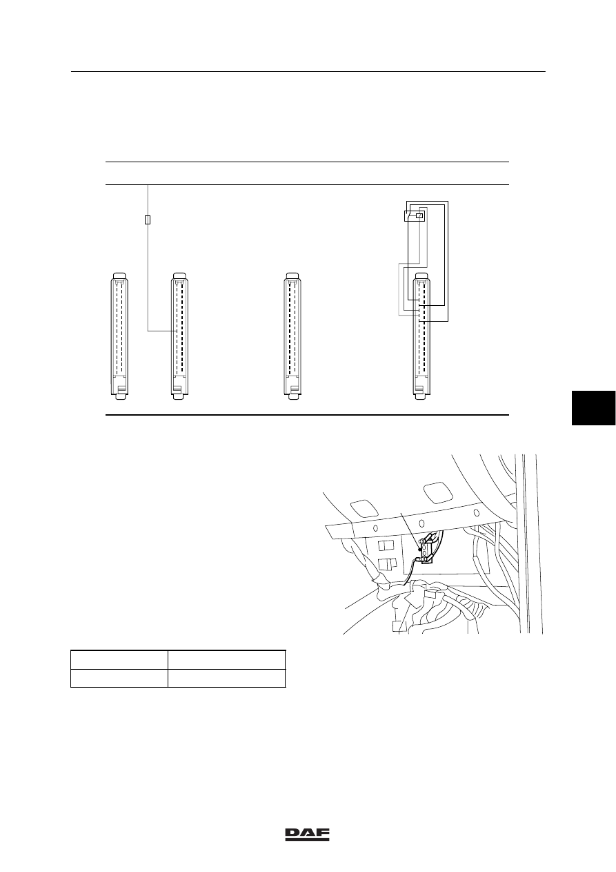
1.1 CONNECTION POINTS ON PRINTED CIRCUIT
401
19
1
35
18
403
19
1
35
18
400
19
1
35
18
402
19
1
35
18
RES
G450
ER01
1010
M
1000
E500914
The accompanying diagram shows the spare
connectors for accessories.
The connectors concerned are fed via the
printed circuit board tracks. It is, therefore,
absolutely essential that the amperages
specified should not be exceeded, since this
might cause burning of the tracks and
overloading of the contact relay.
Maximum current passing through the diodes:
3A
Note:
If necessary, the supply voltage before or after
the contact can also be branched off from the
contact block (A).
The connection points are not fused.
Fuse
Maximum current
ER01
15 A
E500224
A
ǹ 0009
6
5
CONNECTING ACCESSORIES
Connecting accessories
1-2
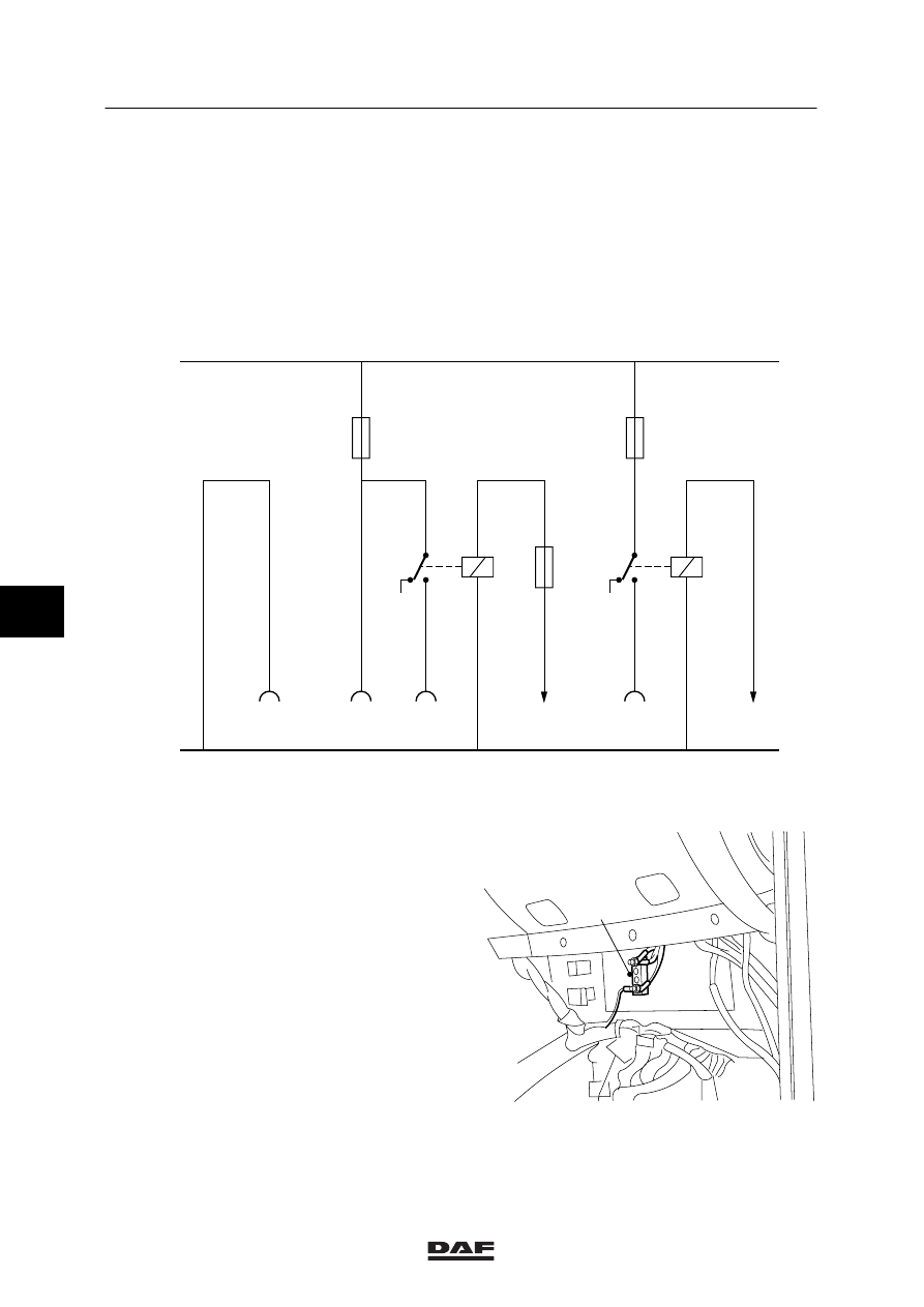
1.2 CONNECTING ACCESSORIES WITH A CURRENT CONSUMPTION OF 15 TO
25 AMP
If amperages of 15 to 25A are required,
assemble a wiring harness for this purpose and
connect it in accordance with the diagram below.
The required relays and fuses should be added,
but they must not be fitted on the printed circuit
board. The wire core should have a
cross-section of at least 2.5 mm2.
W 5 03 002
25.0 A
1
2
15.0 A
1
2
30
85
E027
30
85
86
87
87A
87A
86
87
7.5 A
1106
1130
2161
2102
A027
4
A027
2
A027
1
A027
3
M
1000
Current supply wire 1000 to be branched off
from contact block (A).
Connector A027
Pin 1
current consumption max. 25 A before
contact
Pin 2
current consumption max. 25 A after
contact
Pin 3
earth (the wire core should have a
cross-section of 4 mm
2
because of
possible high currents)
Pin 4
current consumption max. 15 A after
contact
If pins 1 and 2 are both connected, the
maximum combined current consumption after
the contact has been switched on is 25A. With
the contact switched off, the maximum current
consumption of pin 1 is 25A.
E500224
A
6
ǹ 0009
Нет комментариевНе стесняйтесь поделиться с нами вашим ценным мнением.
Текст