DAF LF45, LF55 Series. Manual — part 464
©
200436
3-7
Removal and installation
BRAKE SYSTEM AND COMPONENTS
ΛΦ45/55 series
6
4
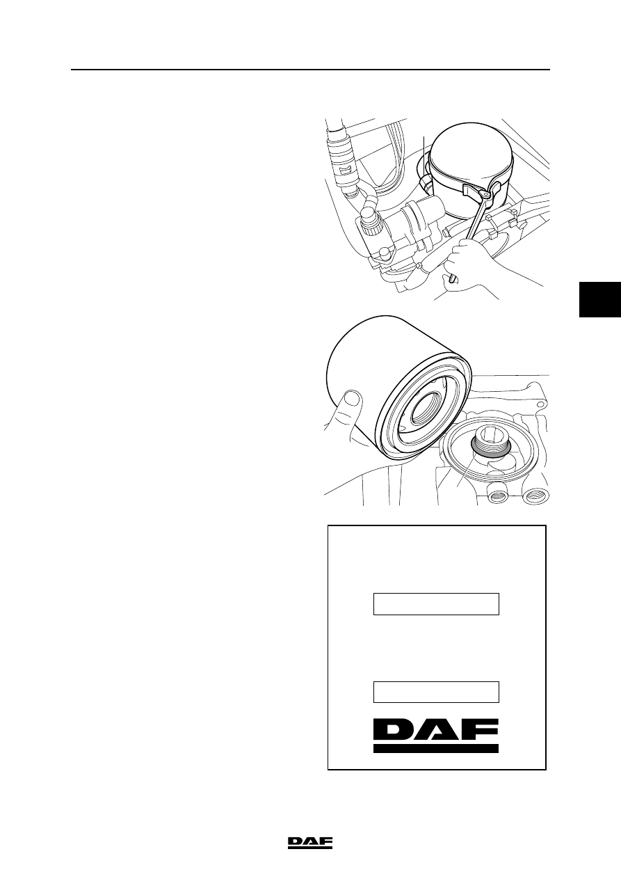
Removing air dryer filter element
1.
Bleed the air dryer by allowing it to
regenerate or by loosening the compressor
pipe (1), so that the interior of the air dryer is
depressurised.
2.
Remove the filter element by turning it anti-
clockwise using a filter strap spanner.
3.
The filter element should be disposed of as if
it were an oil filter.
4.
Clean the air dryer internally.
5.
Check the air dryer threaded connection (2)
for damage and then lubricate it sparingly
with grease.
Installing the air dryer filter element
1.
Lubricate the sealing ring of the new filter
element sparingly with grease.
2.
Fit the filter element by manually tightening it
until the sealing ring abuts. Then tighten the
filter element by hand (approx. 1 turn).
3.
Fasten the compressor line (1).
4.
Pressurise the system and then check the air
dryer for air leaks.
5.
Fill in the date on the sticker with a
waterproof felt pen by which the filter
element must be replaced (max. 1 year after
fitting).
R600525
1
R600526
2
Artikelnummer
Reference
Teilenummer
Référence
Eerstvolgende vervanging
Next change
Nächster Wechsel
Prochain remplacement
1391510
R600523
BRAKE SYSTEM AND COMPONENTS
3-8
©
200436
Removal and installation
4
ΛΦ45/55 series
6
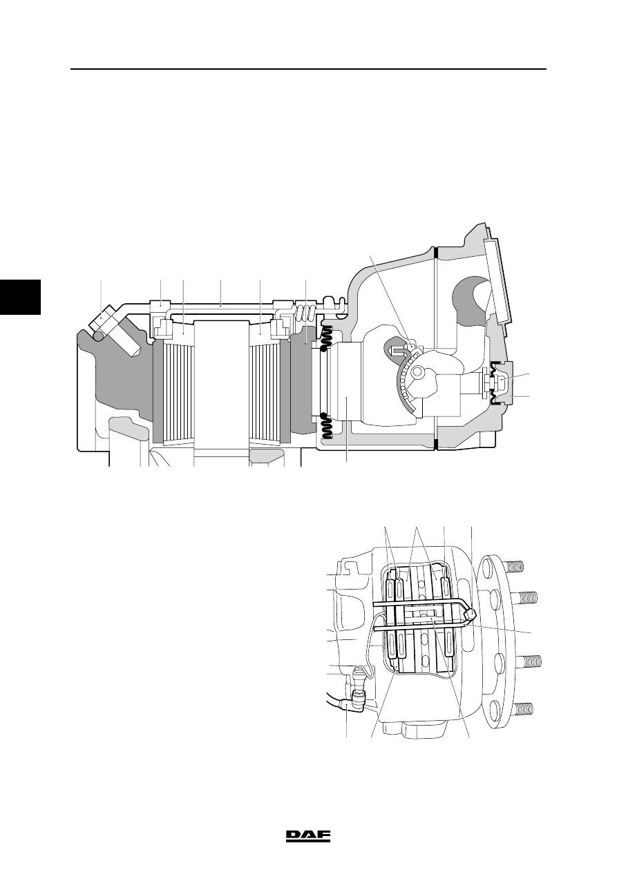
3.7 REMOVAL AND INSTALLATION, BRAKE PADS, WABCO MODEL
Never insert fingers between the
brake calliper and the brake carrier
during and following removal of the
brake pads. Always take hold of the
brake calliper on the outside.
Removing the brake pads
1.
Apply the parking brake.
If the respective axle has spring brake
cylinders, place chocks in front of and behind
the wheels of another axle and release the
parking brake.
2.
Remove the wheels in question.
3.
Remove the connector of the wear sensors.
4.
Remove the bolt (1).
5.
Remove the locking bracket (4).
6.
Remove the spring clips (2).
7.
Remove the strip (10) and wear sensors
from the brake pads.
8.
Remove the cap (8) from the brake adjuster.
9.
Turn the hexagon (7) clockwise with a ring
spanner. Release the brake adjuster.
}
PAN 17 and PAN 19-1+ versions
7
8
9
R600512
6
5
3
3
4
2
1
R600513
2
3
2
1
4
10
5
11
©
200436
3-9
Removal and installation
BRAKE SYSTEM AND COMPONENTS
ΛΦ45/55 series
6
4
Note:
Push back the pressure plate (5) manually, while
releasing the adjuster. This is to ensure that the
pin of the adjusting screw remains in the slot of
the pressure plate. Otherwise, there is a chance
that the adjusting screw will start turning and
damage the gaiter.
10. Remove the brake pads (3) and the pressure
plate.
11. Check the pressure plate, the pressure plate
guide and the brake pad slots for corrosion.
Remove any corrosion carefully with a steel
brush.
12. Shift the brake calliper towards the cylinder.
13. Check the dust covers, guide pins and
adjusting screw for wear and damage.
Replace in the event of damage and/or wear.
14. Shift the brake calliper manually over the
guide pins and check the freedom of
movement in this way.
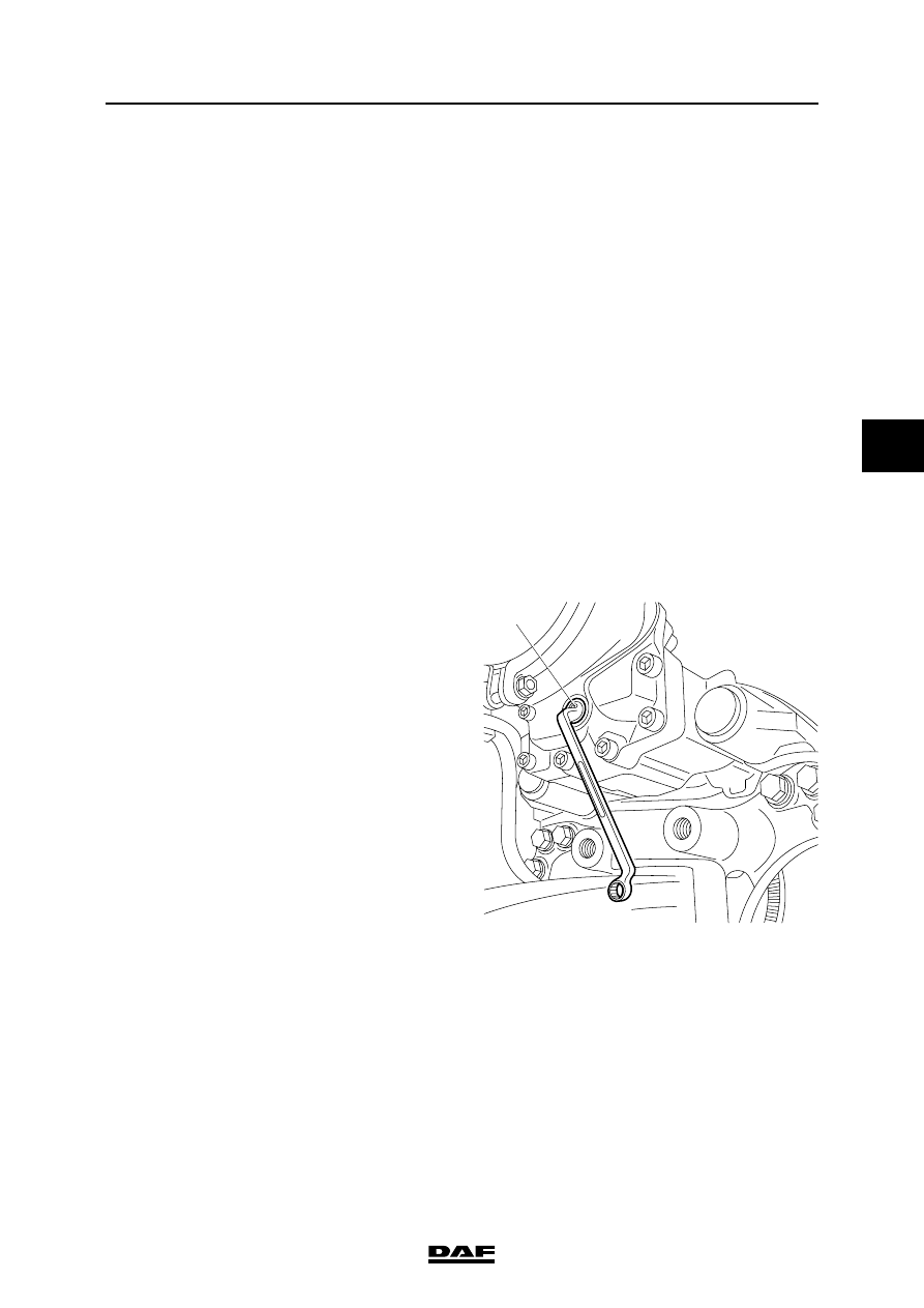
15. Check the brake adjuster.
-
Hold the adjusting screw while turning
the hexagon (7) anti-clockwise. Check
that the piston can move freely.
-
Turn the hexagon (7) completely back
(clockwise).
-
Depress the brake pedal lightly a few
times to check that the automatic brake
adjuster works.
-
Turn the hexagon (7) back (clockwise).
Installing the brake pads
If the brake pads have wear end indicators, they
must be replaced at the same time as the brake
pads, including accessories.
Note:
Brake pads must always be replaced on both
sides of the axle.
1.
If necessary, turn the hexagon (7) back
completely.
2.
Clean the brake pad seats.
3.
Place the pressure plate in the brake calliper
and attach it to the adjusting screw.
4.
First, place a brake pad on the brake piston
side.
5.
Shift the brake calliper towards the wheel
until it touches the brake disc.
R600515
7
BRAKE SYSTEM AND COMPONENTS
3-10
©
200436
Removal and installation
4
ΛΦ45/55 series
6
6.
Now position the other brake pad as well.
7.
Separate the inner brake pad from the thrust
piece.
8.
Position a feeler gauge with the correct
thickness (see "Technical data") between
the brake pad and the pressure plate and
adjust the play using the adjuster with the
hexagonal adjusting bolt.
9.
Turn the hexagon clockwise until the feeler
gauge just fits.
10. Position the new wear sensor with the strip
(10).
11. Position the new spring clips.
12. Position the new locking bracket and tighten
it with the bolt (1). See "Technical data".
13. Fit the wear sensor connector.
14. Fit the cap (8).
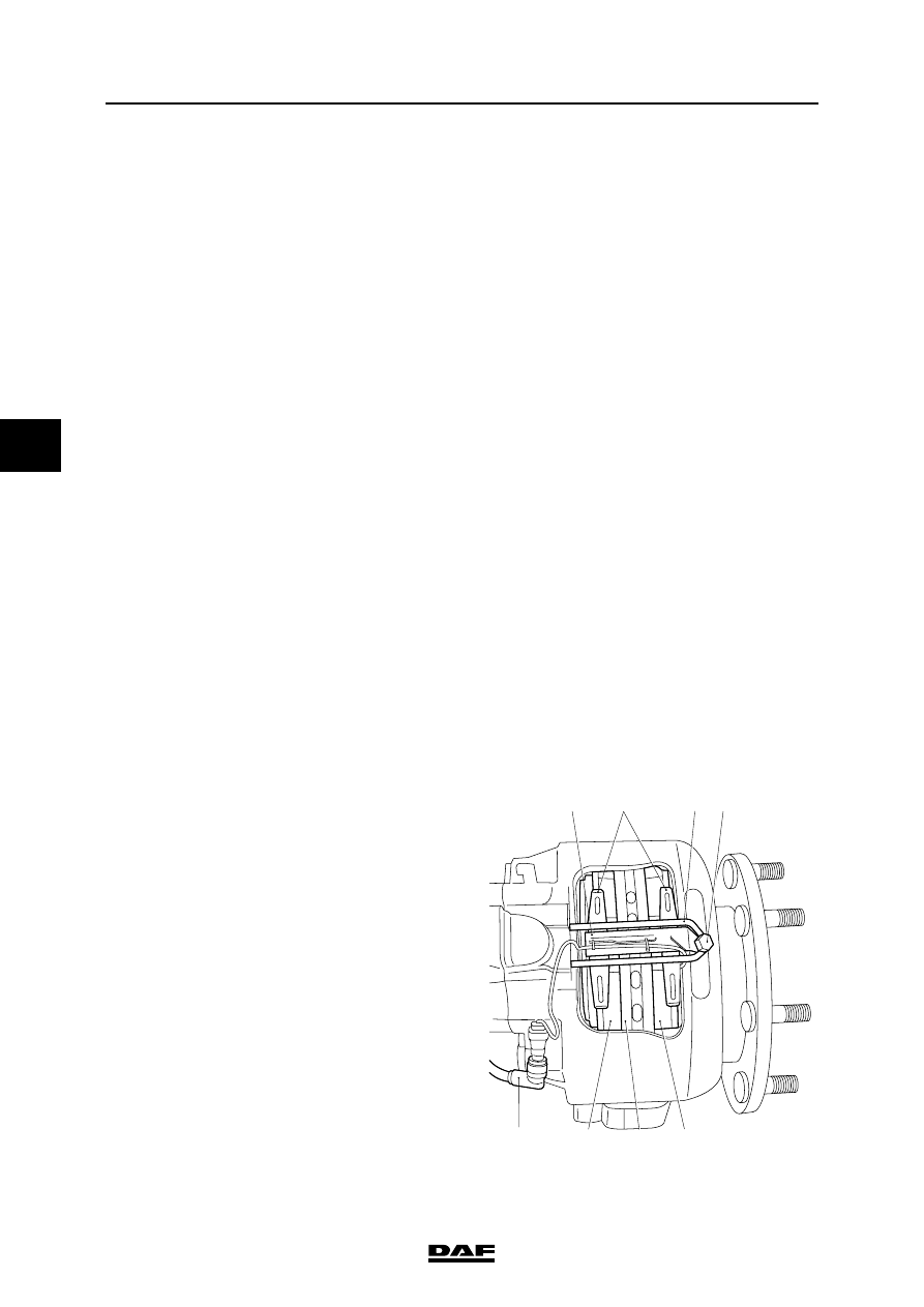
PAN 19-2 version
Removing the brake pads
1.
Apply the parking brake.
If the respective axle has spring brake
cylinders, place chocks in front of and behind
the wheels of another axle and release the
parking brake.
2.
Remove the wheels in question.
3.
Remove the wear sensor connector (7).
4.
Remove the bolt (1).
5.
Remove the locking bracket (2).
6.
Remove the spring clips (3).
7.
Remove the strip (4) and wear sensors from
the brake pads.
8.
Remove the cap(s) from the brake adjuster.
9.
Turn the hexagon (9) clockwise with a ring
spanner. Release the brake adjuster.
10. Remove the brake pads (5).
11. Check the brake pad slots for corrosion.
Remove any corrosion carefully with a steel
brush.
R600571
3
4
1
5
5
7
2
6
Нет комментариевНе стесняйтесь поделиться с нами вашим ценным мнением.
Текст