DAF LF45, LF55 Series. Manual — part 465
©
200436
3-11
Removal and installation
BRAKE SYSTEM AND COMPONENTS
ΛΦ45/55 series
6
4
12. Shift the brake calliper towards the cylinders.
13. Check the dust covers, guide pins and
adjusting screws for wear and damage.
Replace in the event of damage and/or wear.
14. Shift the brake calliper manually over the
guide pins and check the freedom of
movement in this way.
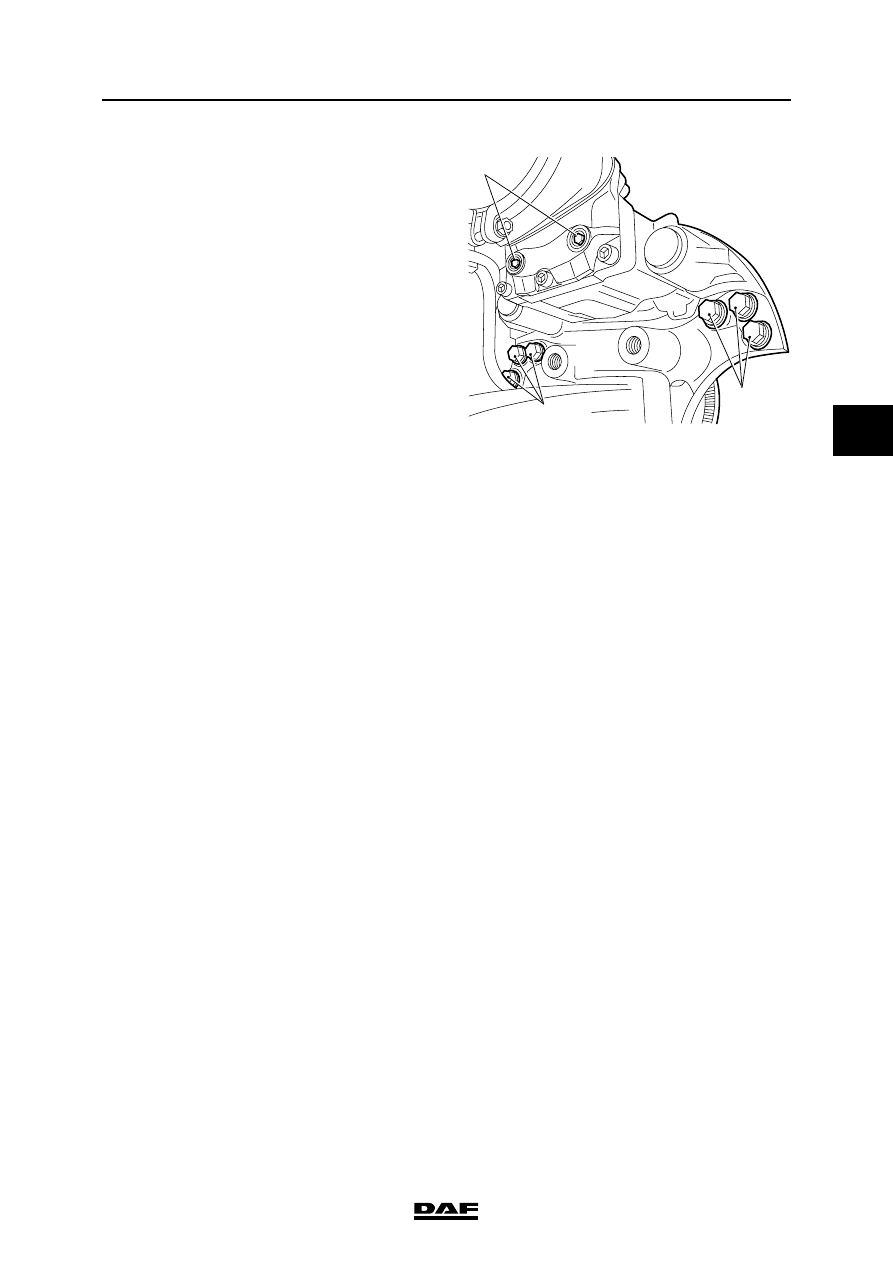
15. Check the brake adjuster.
16. Turn the hexagon (9) completely back
(clockwise).
17. Depress the brake pedal lightly a few times
to check that the automatic brake adjuster
works. Turn the hexagon (9) back
(clockwise).
Installing the brake pads
If the brake pads have wear end indicators, they
must be replaced at the same time as the brake
pads, including accessories.
Note:
Brake pads must always be replaced on both
sides of the axle.
1.
If necessary, turn the hexagon (9) back
completely.
2.
Clean the brake pad seats.
3.
First, place a brake pad on the brake piston
side.
4.
Shift the brake calliper towards the wheel
until it touches the brake disc.
5.
Now position the other brake pad as well.
6.
Separate the inner brake pad from the thrust
pieces.
7.
Position a feeler gauge with the correct
thickness (see "Technical data") between
the brake pad and the thrust piece and adjust
the play using the adjuster with the
hexagonal adjusting bolt.
8.
Turn the hexagon clockwise until the feeler
gauge just fits.
R600572
9
8
8
BRAKE SYSTEM AND COMPONENTS
3-12
©
200436
Removal and installation
4
ΛΦ45/55 series
6
9.
Position the new wear sensor with the
strip (4).
10. Position the new spring clips.
11. Position the new locking bracket and tighten
it with the bolt (1). (See "Technical data").
12. Fit the wear sensor connector.
13. Fit the cap(s) to the brake adjuster.
©
200436
3-13
Removal and installation
BRAKE SYSTEM AND COMPONENTS
ΛΦ45/55 series
6
4
3.8 REMOVAL AND INSTALLATION, BRAKE PADS, KNORR MODEL
Never insert fingers between the
brake calliper and the brake calliper
carrier during and following removal
of the brake pads. Always take hold
of the brake calliper on the outside.
Removing the brake pads
1.
Apply the parking brake.
If the respective axle has spring brake
cylinders, place chocks in front of and behind
the wheels of another axle and release the
parking brake.
2.
Remove the wheels in question.
3.
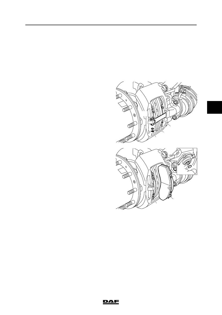
Remove the hairpin spring (26) and washer
(45) from the yoke pin (44) of the locking
strip (11).
4.
Press the strip on and remove the yoke
pin (44).
5.
Check the strip for corrosion; replace if
necessary.
6.
Remove the sealing cap (37).
7.
Using a ring spanner and the adapter, turn
the hexagonal bolt (23) anti-clockwise until
the brake pads (12) can be removed (a
clicking noise can be heard).
Note:
Never turn the hexagonal adjusting bolt
without using an adapter. The adapter is a
torque safety and will break off when the
torque is too high. Without the use of an
adapter the mechanics in the brake calliper
may become damaged when the torque is
too high, so that replacement of the brake
calliper may be necessary.
8.
Remove the brake pads.
}
26
45
11
44
R600461
12
12
R600462
37
23
BRAKE SYSTEM AND COMPONENTS
3-14
©
200436
Removal and installation
4
ΛΦ45/55 series
6
Installing the brake pads
1.
Check the brake calliper play. See
"Inspection and adjustment".
2.
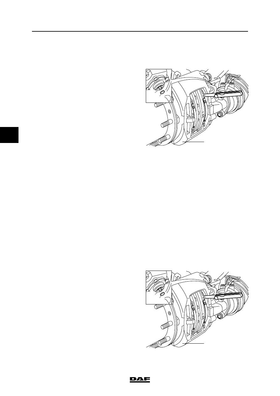
If necessary, turn the hexagonal adjusting
bolt (23) back completely, using the adapter.
3.
Clean the brake pad seats.
4.
Check all brake calliper seals (guide bushes,
thrust pieces).
5.
Shift the brake calliper (1) towards the wheel
side.
6.
Fit the outer brake pad.
7.
Shift the brake calliper towards the brake
cylinder side.
8.
Fit the inner brake pad.
9.
Separate the inner brake pad from the thrust
pieces.
10. Position a feeler gauge with the correct
thickness (see "Technical data") between
the brake pad and the thrust piece of the
adjuster with the hexagonal adjusting bolt.
11. Turn the hexagonal adjusting bolt clockwise
with the ring spanner and the adapter until
the feeler gauge just fits. Remove the feeler
gauge.
12. Check the play between the end of the brake
pads and the brake calliper carrier (see
"Technical data"). If the play is too small,
material must be ground off the steel plate of
the brake pad. If the play is too large, the
brake pads and/or brake carrier must be
replaced.
13. Lightly grease the sealing cap (see
"Technical data") and replace it on the slack
adjuster.
14. Fit the locking strip (11).
15. Press the strip and fit the yoke pin.
16. Fit the washer (45) and the hairpin spring
(26) on the yoke pin (44).
17. Apply the service brake once and check that
the hub can move freely. If necessary,
increase the play.
18. Put the wheels back on.
23
37
1
R600463
23
37
1
R600463
Нет комментариевНе стесняйтесь поделиться с нами вашим ценным мнением.
Текст