DAF LF45, LF55 Series. Manual — part 169
©
200505
4-11
Removing and installing
BE ENGINE
ΛΦ45/55 series
2
2
4.8 REMOVING AND INSTALLING CYLINDER HEAD
When components are removed
from any part of the engine, dirt may
enter. This may cause serious
damage to the engine. The engine
should therefore be cleaned
thoroughly before it is opened. Plug
all openings that are freed.
Removing cylinder head
1.
Drain the coolant.
2.
Disconnect all electrical wiring around the
engine which is required for removing the
cylinder head.
3.
Disconnect the air inlet pipe from the air
cooler on the turbocharger side.
4.
Remove the poly-V-belt.
5.
Remove the heat shields from the exhaust
manifold.
6.
If fitted, remove the attachment bolts of the
air-conditioning compressor.
7.
Remove the attachment bolts from the
alternator/air-conditioning compressor
bracket and remove the attachment bracket.
8.
Remove the attachment bolts from the
exhaust manifold and move the manifold and
the turbocharger a little away from the
cylinder head.
9.
Remove the other coolant hoses that are
attached to the cylinder head.
When removing components from
the fuel system, dirt can enter. This
may result in serious damage. The
area around the fuel system should
therefore be cleaned before opening
it. Detached pipes must be plugged
immediately.
10. Detach the injector pipes on the injector side.
11. Detach the supply pipe between the high-
pressure pump and fuel rail on the fuel rail
side.
12. Detach the fuel return pipe from the fuel rail
and from the cylinder head.
}
}
BE ENGINE
4-12
©
200505
Removing and installing
2
ΛΦ45/55 series
2
13. Unscrew the attachment bolts from the fuel
rail and remove it.
14. Unscrew the attachment bolts from the
intake manifold and remove it.
Note:
To avoid dirt entering the intake opening, it
must be taped up.
15. Remove the valve cover.
16. Remove the valve sleeve.
17. Remove the valve gear.
18. Remove the push rods. Mark the push rods
so that they can be refitted in their original
position.
19. Remove the fuel supply pipes.
20. Remove the injectors.
21. Remove the attachment bolts from the
cylinder head in the reverse order to that
followed for tightening. See "Technical data".
22. Remove the cylinder head from the cylinder
block. Keep the gasket to enable the correct
new head gasket to be selected.
23. Remove any gasket remnants from the
cylinder head and the cylinder block.
24. Check the cylinder block. See "Checking and
adjusting".
25. Check the threaded holes in the cylinder
block for damage and cracking.
26. Check the cylinder head. See "Checking and
adjusting".
Installing cylinder head
1.
Clean the threaded holes in the cylinder
head using a screw tap.
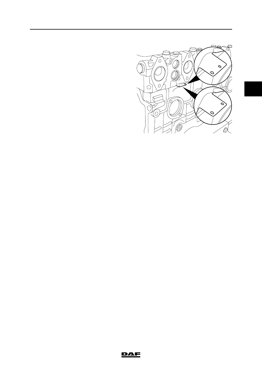
Note:
Cylinder head gaskets are available in two
thicknesses. The thickness of the cylinder
head gasket can be identified by the position
of the holes in the projecting cylinder head
gasket lip under the exhaust manifold on
cylinder 2. See "Technical data" for the
cylinder head gasket thicknesses.
©
200505
4-13
Removing and installing
BE ENGINE
ΛΦ45/55 series
2
2
2.
Position the new cylinder head gasket. If the
type of cylinder head gasket is known, use a
gasket of the same type as the one removed.
Note:
If the type of cylinder head gasket removed
is not known or if the main components of the
driving gear have been changed, the type of
gasket required must be determined afresh.
To do this, measure the average piston
projection. See "Checking and adjusting".
Select the correct type of cylinder head
gasket using the information in "Technical
data" and fit it.
3.
Check that all lubricating and coolant ducts
are free.
4.
Position the cylinder head carefully on the
cylinder block and ensure that the cylinder
head fits well over the dowel pins.
5.
Check the cylinder head bolts. See
"Checking and adjusting". Use new cylinder
head bolts if one bolt does not meet one or
more conditions.
6.
Apply engine oil to the thread and to the
underside of the bolt head.
7.
Position the cylinder head bolts and hand-
tighten them.
Note:
The short cylinder head bolts must be fitted
in the outer rows.
8.
Tighten the cylinder head bolts to the
specified torque and in the sequence shown.
See "Technical data".
9.
Fit the exhaust manifold with new gaskets
and tighten the attachment bolts to the
specified torque. See "Technical data".
10. Fit the injectors.
Note:
Ensure that the injector is fitted correctly,
bearing in mind the supply opening.
11. Fit the fuel supply pipes.
M201230
BE ENGINE
4-14
©
200505
Removing and installing
2
ΛΦ45/55 series
2
12. Fit the push rods in their original position and
apply a drop of engine oil to the head of the
push rod.
13. Fit the valve gear.
14. Fit the valve sleeve.
15. Tighten the injector wiring to the specified
torque. See "Technical data".
16. Fit the valve cover.
17. Remove any gasket remnants from the
intake manifold and the cylinder head.
Note:
Ensure that the air inlet is free of gasket
remnants.
18. Apply sealant to the intake manifold and fit it.
See "Technical data".
19. Fit the fuel rail.
20. Fit the injector pipes.
21. Fit the supply pipe between the high-
pressure pump and fuel rail.
22. Fit the fuel return pipe on the fuel rail and
cylinder head.
23. Connect the various coolant hoses.
24. Fit the bracket of the alternator/air-
conditioning compressor.
25. If present, fit the air-conditioning
compressor.
26. Fit the poly-V-belt.
27. Fit the heat shields.
28. Fit the air inlet pipe of the air cooler on the
turbocharger side.
29. Connect the electrical wiring.
Нет комментариевНе стесняйтесь поделиться с нами вашим ценным мнением.
Текст