DAF LF45, LF55 Series. Manual — part 392
12
1427090/03
EL001573
1
2
3
4
5
6
7
8
9
10
11
12
13
14
15
16
17
18
19
20
21
22
23
24
25
26
27
28
29
30
31
32
33
34
35
36
37
38
39
40
41
42
43
44
45
46
47
48
49
50
51
52
53
4601
4602
4602
4601
4601
4601
4602
3412
4602
4684
1240
4684
3412
3412
3412
3412
4601
4601
4601
4601
3412
3479
3412
B5/703
B10/702
4
762
B11
713
A8
718
4
824
4
786
2
786
A13
713
A000
41
5
765
C020
1
2
5
764
C021
1
2
12
762
G520
G520
1
765
3
786
1
764
8/707
24/
748
D851
D32/
746
D900
B16/
744
D26/
746
B5/
797
D911
D942
1010
1000
1010
1000
1209
E013
10A
E282
15A
G036
3
1
24
5
1356
4601
F009
2
1
3
4
E587
1
2
E091
2
8
A070
3
!
!
!
D758
798
798
200440
2-57
5
ELECTRICAL SYSTEM
Electrical system
series
45/55
LF

13.
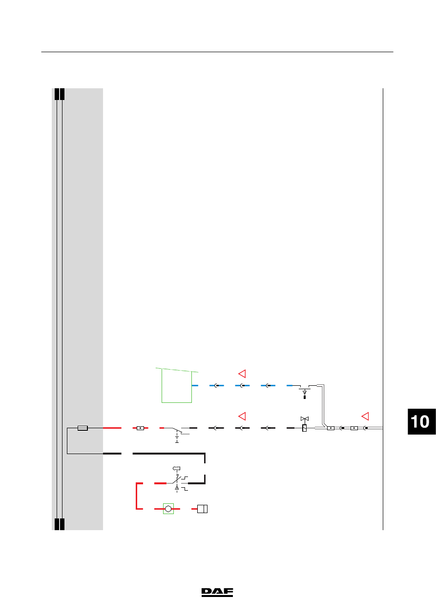
DIFFERENTIAL
L
OCK
If
the
contact
switch
(C841)
is
activated,
a
voltage
is
applied
through
fuse
E018
and
wire
1217
to
the
switch
for
the
cross-axle
dif
ferential
lock
(C748).
If
switch
C
748
is
operated,
a
voltage
is
applied
to
the
operating
valve
for
the
cross-axle
dif
ferential
lock
(B243)
through
wire
4517.
If
the
dif
ferential
is
locked,
the
dif
ferential
lock
control
switch
(F006)
connects
pin
C
34/745
of
the
V
IC
to
earth
via
wire
3408.
The
V
IC
will
activate
the
D
IP
through
I-CAN
to
switch
on
the
“dif
ferential
lock
switched
on”
indicator
.
VARIANTS
Location 17,21
Connector
762:
N
otf
itt
edo
nv
eh
ic
let
yp
eF
T
200440
2-58
5
ELECTRICAL SYSTEM
Electrical system
series
45/55
LF
13
1427090/03
EL001574
1
2
3
4
5
6
7
8
9
10
11
12
13
14
15
16
17
18
19
20
21
22
23
24
25
26
27
28
29
30
31
32
33
34
35
36
37
38
39
40
41
42
43
44
45
46
47
48
49
50
51
52
53
4001
1217
4001
1217
4517
4517
4517
4517
3408
3408
3408
3408
1000
1000
1000
E349
1
2
1/708
A10/702
D942
1010
1000
1010
1000
E018
15A
4001
2
766
9
762
A4
713
1
766
8
762
B9
713
12
762
3
766
G520
5
71
0I
C748
F006
2
1
2
1
B243
D900
C34/
745
C841
1/808
2/808
4/808
6/808
!
!
!
200440
2-59
5
ELECTRICAL SYSTEM
Electrical system
series
45/55
LF
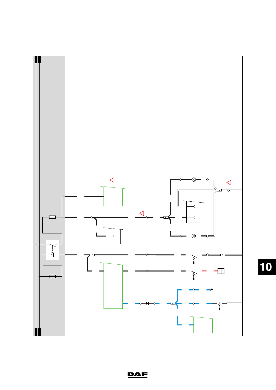
14.
INTERIOR
LIGHTING
Power
is
supplied
to
the
door
switches
(E514
and
E515)
through
fuse
E028
and
wire
1107.
If
the
door
on
the
driver
’s
side
is
opened,
door
switch
E514
is
activated
(connection
between
1
and
2).
A
s
a
result,
power
will
be
supplied
via
w
ire
2600
to
the
left-hand
stepwell
lighting
(C062)
and
to
pin
D
1/746
of
the
V
IC
(D900).
The
V
IC
also
turns
on
the
interior
lighting
(C1
19)
via
pin
A4/743,
provided
that
the
switches
are
in
the
correct
position.
At
the
same
time,
a
voltage
signal
is
applied
to
the
alarm
syst
em
elect
ronic
unit
(D91
1)
If
the
alarm
syst
em
was
act
ivat
ed,
it
can
be
triggered
in
this
way
to
activate
the
alarm
horn
and
hazard
w
arning
lights.
Switch
E515
provides
exactly
the
same
function
on
the
co-driver
’s
side.
When
the
door
on
the
driver
’s
side
is
closed
(contact
between
1
and
2
interrupted),
power
is
no
longer
supplied
to
pin
D1/746
of
the
V
IC.
From
this
moment,
pin
A4/743
will
continue
to
be
supplied
w
ith
power
for
about
another
9
seconds.
When
the
vehicle
ignition
is
switched
on,
the
power
supply
to
pin
A4/743
of
the
V
IC
will
cease
immediately
.The
lighting
w
ill
be
switched
of
fi
mmediately
.
In
an
SL
cab,
the
bunk
lights
(C1
10
and
C1
11
)
receive
power
through
fuse
E028.
Operating
the
switches
in
the
bunk
lights
turns
the
lights
on.
The
interior
lighting
(C1
19)
also
contains
a
bunk
light
function
that
is
activated
in
exactly
th
es
am
ew
ay
.
200440
2-60
5
ELECTRICAL SYSTEM
Electrical system
series
45/55
LF
Нет комментариевНе стесняйтесь поделиться с нами вашим ценным мнением.
Текст