DAF LF45, LF55 Series. Manual — part 328
©
200416
4-1
Removal and installation
CE ENGINE INLET/EXHAUST SYSTEM
ΛΦ45/55 series
4
6
4. REMOVAL AND INSTALLATION
4.1 REMOVAL AND INSTALLATION, TURBOCHARGER
If the turbocharger to be replaced
has been damaged to such an extent
that parts of it are missing or
lubricating oil has entered the inlet
system, the inlet and exhaust
systems must be checked and
cleaned thoroughly in order to
prevent serious damage to the
engine.
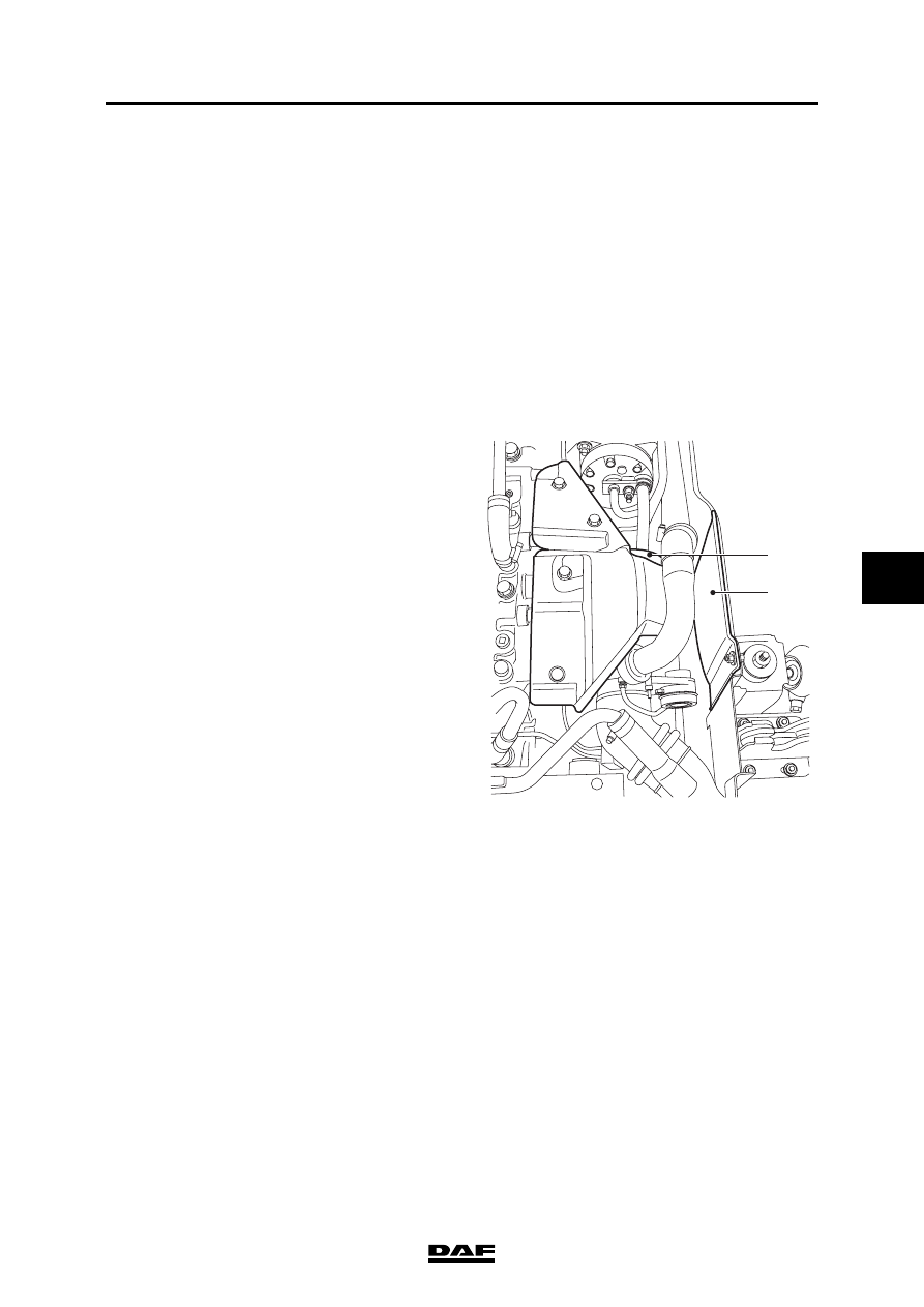
Removing the turbocharger
1.
Remove the right-hand engine
encapsulation (2).
2.
Remove the heat shield (1) from the oil filter.
3.
Remove each charge pipe and the
turbocharger exhaust pipe.
4.
Remove the oil discharge pipe from the
turbocharger.
5.
Detach the entire oil supply pipe from the oil
filter housing to the turbocharger.
6.
Remove the attachment bolts from the
turbocharger.
7.
Remove the turbocharger.
8.
Immediately plug the openings.
Installing the turbocharger
1.
Clean the turbocharger and the oil supply
and discharge pipes.
2.
Before installing the turbocharger, check the
following:
-
the turbocharger housing and connector
flange for cracks. See "Technical data"
for rejection standards;
-
the turbocharger shaft must be able to
rotate freely;
-
the turbocharger shaft must not run out
of true;
-
the turbocharger pump and turbine
wheels must not be damaged;
-
there must not be an excessive amount
of oil in the compressor side of the
turbocharger. A small amount of oil on
the inside walls of the compressor side
is allowed.
}
1
i400857
2
CE ENGINE INLET/EXHAUST SYSTEM
4-2
©
200416
Removal and installation
6
ΛΦ45/55 series
4
3.
Check the adjustment of the turbocharger
wastegate. See "Inspection and adjustment".
4.
Check the axial bearing play of the
turbocharger; see "Inspection and
adjustment".
5.
Check the radial bearing play of the
turbocharger; see "Inspection and
adjustment".
6.
Clean the sealing surfaces.
Note:
Always use new gaskets when installing the
turbocharger.
7.
Apply a layer of Copaslip to the exhaust
manifold studs.
8.
Fit the turbocharger to the exhaust manifold.
9.
Fit the attachment nuts and tighten them to
the specified torque. See "Technical data".
10. Check that the oil supply and discharge
pipes are clean and not blocked, kinked or
cracked. Replace the pipes if necessary.
Note:
If the turbocharger oil supply and/or
discharge does not function properly, this
may result in serious damage to the
turbocharger and/or engine.
11. Fit new O-rings to the oil discharge pipe and
apply a thin layer of engine oil to them. Fit the
oil discharge pipe. For the specified
tightening torque, see "Technical data".
12. Pour clean engine oil into the oil supply of the
turbocharger and fit the oil supply pipe, after
fitting a new copper ring, on the oil filter
housing and the turbocharger. Tighten the
pipe to the specified tightening torque; see
"Technical data".
©
200416
4-3
Removal and installation
CE ENGINE INLET/EXHAUST SYSTEM
ΛΦ45/55 series
4
6
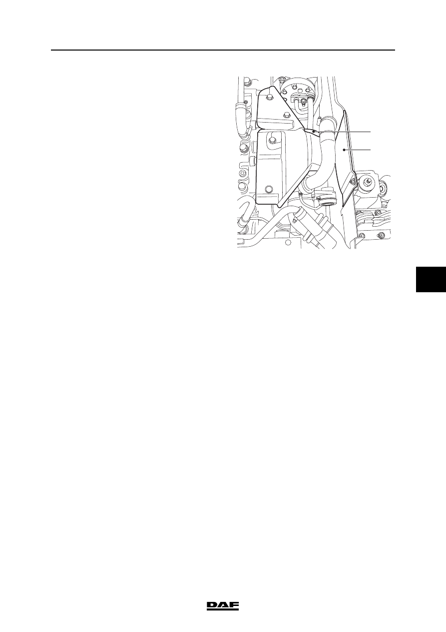
13. Fit the exhaust pipe to the turbocharger.
14. Fit the charge pipes to the exhaust pipe.
15. Fit the heat shield (1) to the oil filter.
16. Install the engine encapsulation (2).
1
i400857
2
CE ENGINE INLET/EXHAUST SYSTEM
4-4
©
200416
Removal and installation
6
ΛΦ45/55 series
4
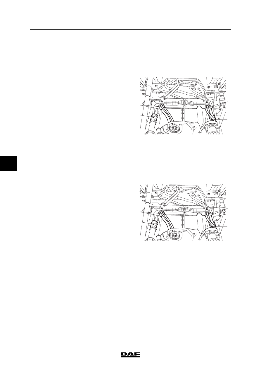
4.2 REMOVAL AND INSTALLATION OF AIR COOLER
Removing the air cooler
1.
Disconnect the earth lead from the battery
terminal.
2.
If the vehicle has air conditioning, loosen the
support of the refrigerant pipes (2) on the
radiator and remove the condenser from the
air cooler supports.
3.
Loosen the support of the coolant pipes (1)
on the radiator.
4.
Remove the charge pipes (3) from the air
cooler and plug the openings.
5.
Disconnect the air cooler.
6.
Remove the air cooler.
Installing the air cooler
1.
Clean the outside of the air cooler with
compressed air.
2.
Install the air cooler and tighten the air cooler
attachments.
3.
Fit the charge pipes (3) to the air cooler.
4.
Fit the bracket of the coolant pipes (1) on the
radiator.
5.
If the vehicle has air conditioning, fit the
condenser in the air cooler supports and
tighten the support of the refrigerant pipes
(2) on the radiator.
6.
Connect the battery terminals.
7.
Start the engine and check for leakage.
i400822
2
3
1
3
i400822
2
3
1
3
Нет комментариевНе стесняйтесь поделиться с нами вашим ценным мнением.
Текст