DAF LF45, LF55 Series. Manual — part 346
5
LF45/55 series
Removal and installation
WIRING REPAIR
2-15
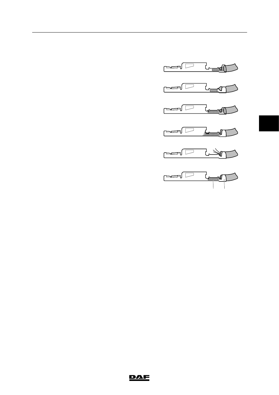
Examples of wire-contact connections
A. Wire not sufficiently slid forwards.
The wire is not sufficiently slid forwards to
ensure a proper current transfer and pull
relief.
B. Stripped part of the wire too short.
The stripped part of the wire is too short to
ensure a proper current transfer whereas a
part of the insulation is clamped underneath
the contact press part.
C. Wire too far backwards.
If the stripped part of the wire is too long
and the wire is placed correctly relative to
the contact press part, the pull relief will
cover too little of the wire.
D. Wire too far forwards.
If the stripped part of the wire is too long
and the wire is placed correctly relative to
the pull relief, the copper conductors at the
front will stick out too far past the contact
press part.
E. Copper conductors not clamped.
Copper conductors not clamped may cause
a short circuit to other wires nearby.
F. This is a correct connection.
E501499
A
B
C
D
E
F
1
2
3
200440
5
WIRING REPAIR
Removal and installation
LF45/55 series
2-16
2.4 FITTING A SCAT SEAL
SCATs are used in places where wires are
exposed to heavy conditions (environment or
application of the vehicle), with the risk of water
entering the connector.
The SCAT seal, which is made of silicone,
prevents corrosion inside the connector and
keeps the seal properties intact in the event of
temperature changes.
The SCAT seal is pressed around the wire with
the relief part of the contact.
The SCATs are available in various colours and
sizes.
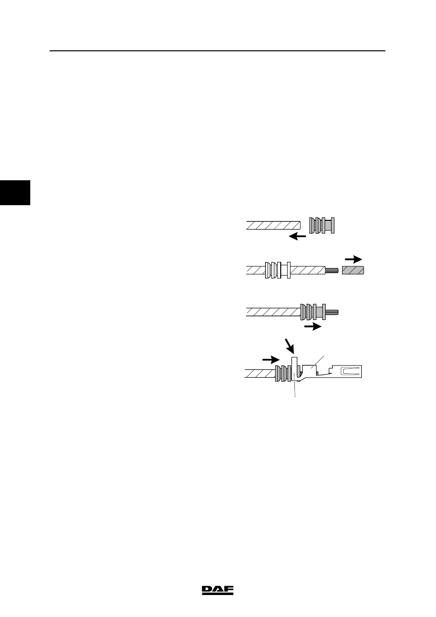
1. Select the right SCAT for the wire, contact
and connector.
2. Slide the SCAT onto an unstripped wire (A).
3. Slide the SCAT far enough onto the wire
and strip the wire to the proper length (B).
4. Slide the SCAT back to the tip of the
stripped wire so that the copper just sticks
out of the SCAT (C).
5. Place the contact in the proper manner (D)
around the SCAT (2) and the stripped
wire (1).
6. Now crimp the contact around the SCAT
and the wire using the proper crimping tool.
E501503
2
1
A
B
C
D
3
200440
5
LF45/55 series
Removal and installation
WIRING REPAIR
2-17
2.5 FITTING AN ELECTRICAL BUFFER CONNECTION
A buffer connection is made when at least two
wire ends must be connected to one another.
This may be required because of a wire repair or
if a wire is to be added to a connection.
Note:
When adding a new wire to an existing wire,
both wires must be of the same thickness.
If part of the existing wire is to be removed, try
to make sure that the wire number can still
easily be found on the wire.
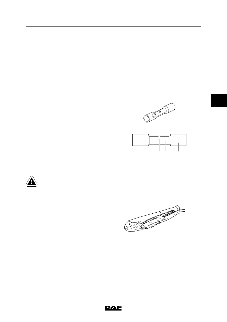
The contact crimping part (1) is the electrical
connection to the stripped wire part. The central
stop (2) is a limiter, preventing the wire to be
connected from being inserted too far. The
insulation is a crimp insulating sleeve with glue
layer (3), which, after heating by a blow drier, will
offer protection against unwanted electrical
contact and corrosion.
There are three different buffer connectors
available: red, blue and yellow. Depending on
the wire thicknesses to be connected (and
possibly the number of wires to be connected) a
specific colour must be used.
- red
diameter 0.25 - 0.75 mm
2
- blue
diameter 1.0 - 2.5 mm
2
- yellow
diameter 4.0 - 6.0 mm
2
Connecting more than two wires to
one another is not recommended.
The glue layer of the crimping
insulation is not sufficient to seal all
resulting gaps. So this is certainly
not permitted outside the cab.
E501489
3
1
1
3
2
It is very important to carry out contact crimping
in the correct way to prevent electrical faults. For
cold fusion a contact crimping tool is required.
This tool creates a cold fusion between wire and
buffer connector.
E501491
3
200440
5
WIRING REPAIR
Removal and installation
LF45/55 series
2-18
Fitting the contact crimp connector
1. Select the right buffer connector for the
wires to be connected.
Note:
If three wires of the same diameter have to
be connected after all, choose a buffer
connector that is the same diameter as two
of the wires. The single wire on the other
side must be stripped to double length and
folded double.
The same applies when a wire is used on
one side that is twice the diameter of the
other.
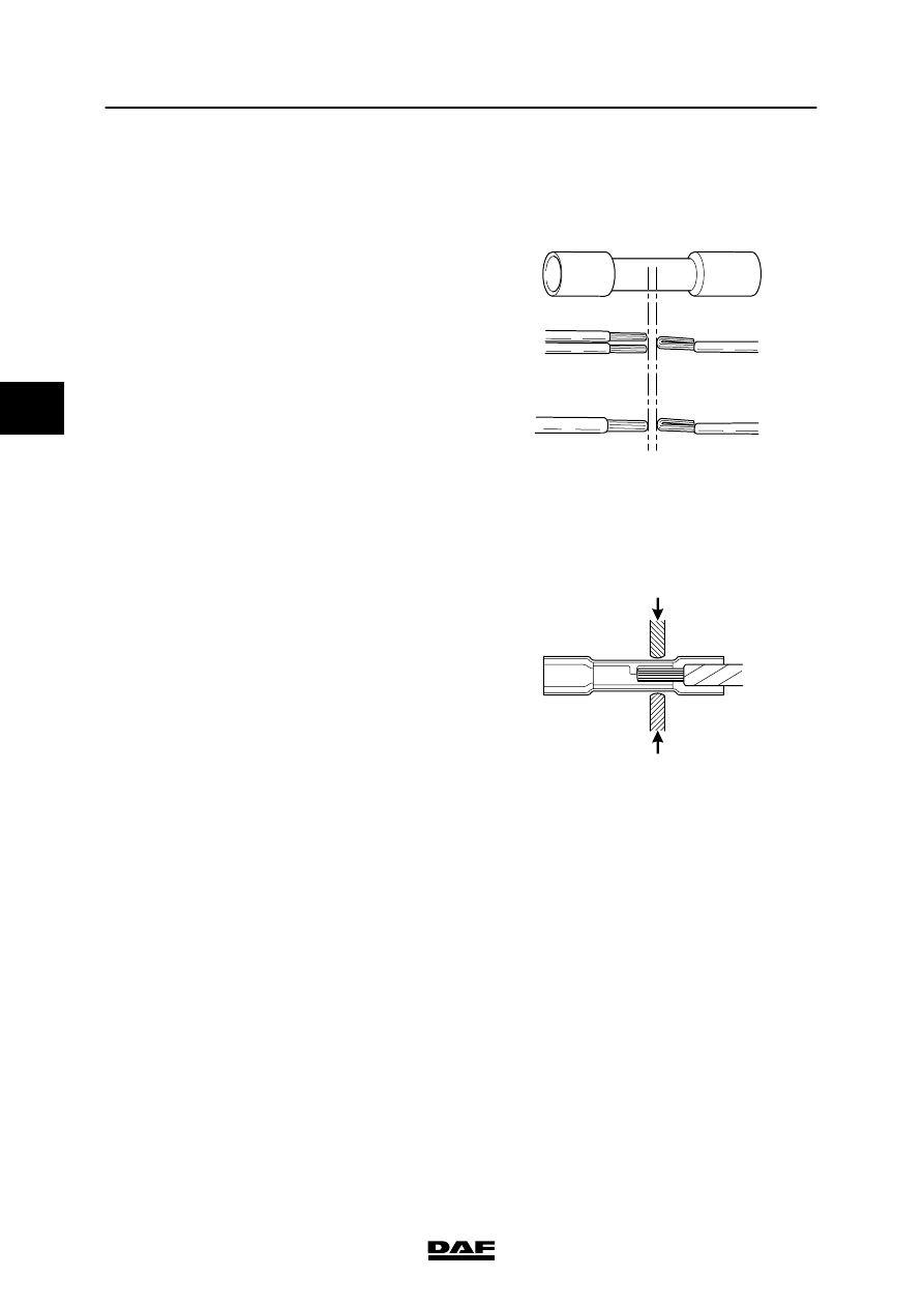
2. Strip the wire to a length of 4 to 5 mm.
Note:
The stripped wire tip may not be twisted.
3. Choose the proper contact crimping tool on
the basis of the buffer connector and wire
diameter, and check the holes to be used.
E501490
4. Place the buffer connector in the hole of the
tool and clamp it gently so the buffer
connector will remain in the hole.
5. Slide the stripped wire ends into the side of
the buffer connector that is engaged by the
contact crimping tool.
Note:
The insulation of the wire may not be slid
into the contact part of the buffer connector.
E501492
3
200440
Нет комментариевНе стесняйтесь поделиться с нами вашим ценным мнением.
Текст