DAF LF45, LF55 Series. Manual — part 345
5
LF45/55 series
Removal and installation
WIRING REPAIR
2-11
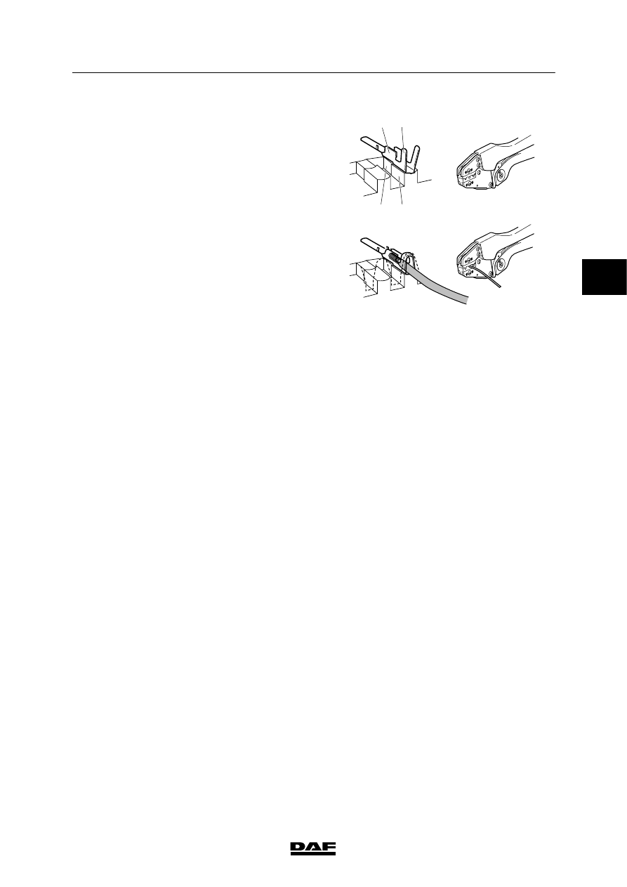
1. Place the wire in the contact.
2. The stripped wire part, the copper
conductor, must be in the contact press
part (1).
The wire insulation must be in the relief
part (2).
3. Check again whether the wire is in the
correct position in the contacts (1 and 2)
and press the contact press parts (3 and 4)
together.
4. Do not interrupt the contact pressure before
the tool is completely compressed in the
end position. Only then is full contact
pressure reached and the tool can be
opened.
E501502
3
4
1
2
3
200440
5
WIRING REPAIR
Removal and installation
LF45/55 series
2-12
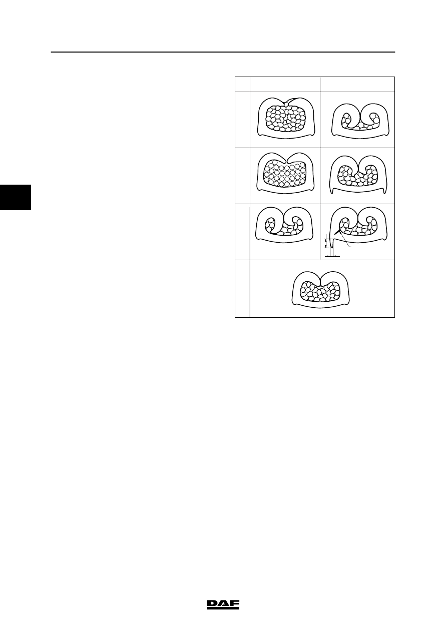
Copper connection
1A. Wire diameter too large
1B. Wire diameter too small
2A. Crimp height too great (hole in crimping tool
too large)
2B. Crimp height too small (hole in crimping tool
too small)
3A. Asymmetric crimping
3B. Asymmetric crimping
4. Proper contact crimping
S = material thickness
x = cracking
1A.
There is a risk that copper
conductors could stick out, which
would adversely affect the fixed
position of the other copper
conductors. This may result in a
short circuit and loose contact.
1B.
The contact may crack and the
copper conductors may not be
sufficiently fixed in the contact.
2A.
Copper conductors are not
sufficiently fixed in the contact.
The wire will come loose of the
contact.
2B.
The contact will be damaged. The
contact may crack after some
time and the wire will then come
loose from the contact.
3A and B
The contact will be damaged and
the copper conductors are not
fully fixed in the contact. The wire
may come loose. The height of
any bulge on the contact may not
exceed the material thickness of
the contact. The width of this
bulge may not exceed half the
material thickness.
E501494
1
A
B
2
3
4
Bmax=1/2S
X
Hmax=S
3
200440
5
LF45/55 series
Removal and installation
WIRING REPAIR
2-13
Insulation connection
Different types of crimping are allowed:
1. normal crimping: the two sides of the relief
part fully engage the insulation.
2. double crimping: two wires are clamped in
one contact.
3. overlap crimping: the two sides of the relief
part engage one another slightly.
4. double overlap crimping: two wires are
clamped in one contact, the two sides of the
relief part engaging one another slightly.
A. If the insulation connection is correct, the
wire is clamped in the relief part with the
correct pressure and the insulation is not
broken.
B. If the contact pressure is too high the
insulation could break, possibly causing a
short circuit.
This may for instance be caused by:
-
using the wrong crimping tool
-
using an improper hole in the crimping
tool (too small)
-
a defect in the crimping tool delaying
the interruption of the contact pressure.
C. If the contact pressure is not sufficient the
insulation may not be clamped and the wire
may come loose. This will interrupt the
electrical connection but may also result in
a short circuit.
This may for instance be caused by:
-
using the wrong crimping tool
-
using an improper hole in the crimping
tool (too big)
-
interrupting the contact pressure
prematurely.
3
200440
5
WIRING REPAIR
Removal and installation
LF45/55 series
2-14
E501511
B
A
C
1
2
3
4
1. Normal crimping
A. Proper insulation connection
2. Double crimping
B. The insulation is broken
3. Overlap crimping
C. The insulation is not secured
4. Double overlap crimping
With double crimping the thinnest wire is
always at the bottom.
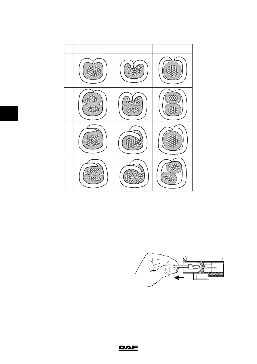
A connection can be checked by gently pulling
the wire after the contact is placed in the
connector. The lock of the locking bolt in the
connector should then be felt.
E501501
3
200440
Нет комментариевНе стесняйтесь поделиться с нами вашим ценным мнением.
Текст