DAF LF45, LF55 Series. Manual — part 476
©
200436
1-1
General
BRAKING PERFORMANCE AND BRAKE EQUALISATION
ΛΦ45/55 series
6
5
1. GENERAL
1.1 INTRODUCTION
How is a good braking performance of a vehicle
combination (truck and trailer vehicle) achieved
while still guaranteeing interchangeability both for
new vehicle combinations and for combinations
following brake reconditioning?
The vehicles should meet the legal requirements
and all settings should be in accordance with the
directives. However, adhering to the directives
does not necessarily mean that there will be no
brake problems.
BRAKING PERFORMANCE AND BRAKE EQUALISATION
1-2
©
200436
General
5
ΛΦ45/55 series
6
1.2 WHAT IS A VEHICLE COMBINATION WITH A GOOD BRAKING
PERFORMANCE?
A vehicle combination of which, in laden condition
and with a 1 to 3 bar pressure at the service
coupling head, the braking deceleration of the
tractive unit is the same or virtually the same as
that of the drawn vehicle.
When problems occur which are related to the
brake system, such as excessive brake-lining
wear, brake vibrations or the vehicle pulling to
one side during braking, the cause should
primarily be sought in an unbalanced distribution
of braking forces.
-
for vehicle combinations:
-
between prime mover and trailer
vehicle.
Fn
Gd
F
Fn
Gd
F
Z
m.a
Fn
Gd
F
Fn
Gd
F
Fn
Gd
F
Z
G
G
m.a
R600023
G =
weight
m =
mass
a =
deceleration (m x a is the force
changing the axle load)
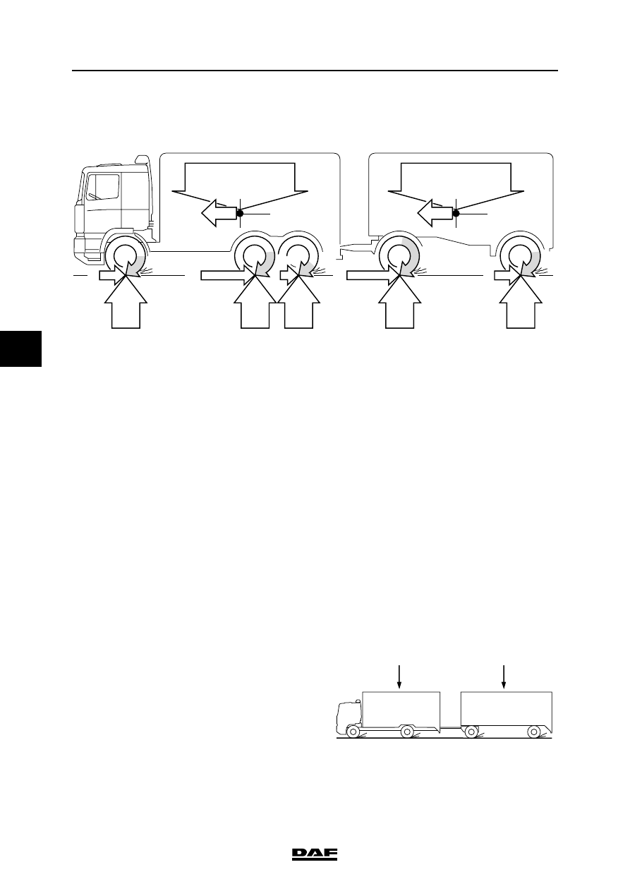
Dynamic axle load: during braking, changes the
load on each axle.
F =
braking force (Fmax = Gd x m)
Gd =
dynamic axle load
m =
the friction coefficient between tyre and
road
Fn =
braking force of the wheel brake
a
R600024
a
©
200436
1-3
General
BRAKING PERFORMANCE AND BRAKE EQUALISATION
ΛΦ45/55 series
6
5
-
for rigid vehicles:
-
between the different axles.
Conditions for a practical distribution of
braking forces
-
Both the prime mover and the trailer vehicle
should have a sufficiently effective brake
system without mechanical defects or
failures in the air system.
With vehicle combinations the braking
performance level of the trailer vehicle may be
noticeably lower than that of the truck. This
means that the prime mover has to provide a
disproportionately large part of the deceleration
required for the total vehicle combination. As the
brakes of the trailer vehicle will consequently be
subjected to low loads only, their condition will
deteriorate (risk of glazing), which will lead to
even higher overloading of the prime mover
brakes. It is therefore important that the
adjustment is correct, as dangerous situations
can arise where the trailer is jostling the prime
mover.
Possible causes of poor braking performance
of a trailer vehicle
-
unduly large brake-chamber stroke.
-
damaged diaphragms in the brake
chambers.
-
greasy, glazed or fully worn linings.
-
the mechanical part of the wheel brake does
not operate smoothly.
-
a leak in the brake system.
-
a blockage in the brake pipe system.
-
not all the valves are in good working order.
-
incorrect setting of the load-sensing valve.
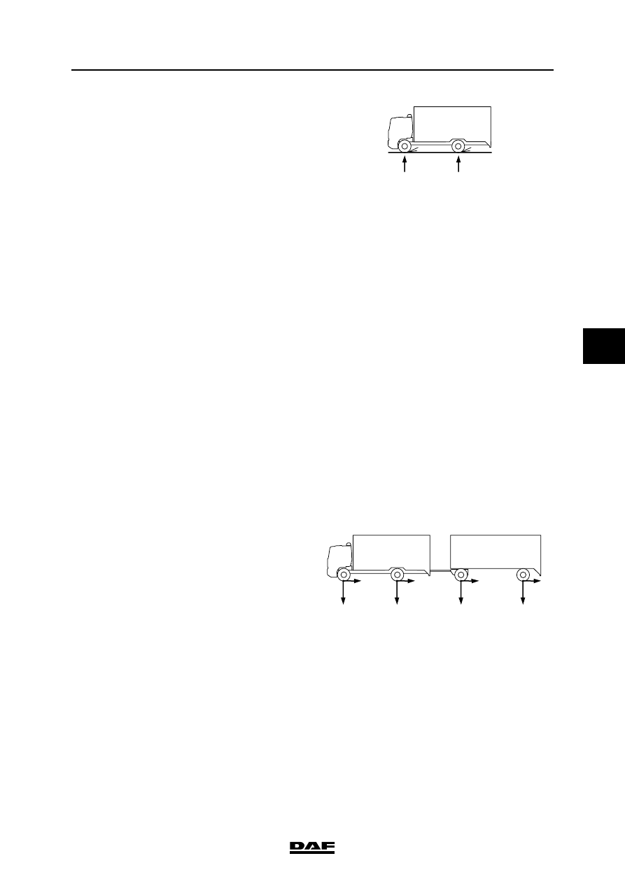
The starting point is that the braking forces
between the axles of the vehicle combination
should be distributed in proportion to the axle
loads. This will also distribute the temperature
correctly over the axles.
Whether this will give the correct distribution
between prime mover and trailer vehicle depends
not only on the quality of the two brake systems,
but also on a correct balancing of the brake
pressures. The latter can be achieved by
adjusting the advance between tractor and drawn
vehicle in such a way that at the most frequently
used brake pressures, i.e. 2-3 bar on the service
line, the braking performance of the prime mover
is the same as that of the trailer vehicle.
This can entail a change in the brake pressure
advance set by the factory.
a
a
R600025
R600026
m1
m3
m4
F1
F :
1
F2
F3
F4
F2 F3
4
m 2
m1
m3 m4
m 2
:
F
:
=
:
:
:

BRAKING PERFORMANCE AND BRAKE EQUALISATION
1-4
©
200436
General
5
ΛΦ45/55 series
6
1.3 BRAKE EQUALISATION MEASUREMENT BY MEANS OF BRAKE
DYNAMOMETER
1.
Make sure the vehicle combination is in
laden condition. A laden combination
makes for a more reliable and accurate
measurement. Furthermore, the maximum
braking performance will be achieved when
the vehicle combination is in laden condition.
2.
The braking forces must be measured on a
system with warm brakes. (Normal operating
temperature.)
3.
The brake linings must have been bedded in.
Only then can a reliable verdict on the
braking forces be obtained.
4.
Write down the braking forces of the various
axles on the "brake equalisation form for
brake dynamometer" at the following brake
pressures, measured at the service coupling
head:
p = 0.5 - 1.0 - 1.5 - 2.0 - 3.0 - 4.0 - 5.0 bar.
5.
Using the data on the "brake equalisation
form for brake dynamometer", calculate the
braking deceleration percentages.
6.
Plot the calculated values in the "brake
equalisation form for brake dynamometer" in
the appropriate EC band graph and evaluate
the measured brake equalisation.
p
R600028
Нет комментариевНе стесняйтесь поделиться с нами вашим ценным мнением.
Текст