DAF LF45, LF55 Series. Manual — part 477
©
200436
1-5
General
BRAKING PERFORMANCE AND BRAKE EQUALISATION
ΛΦ45/55 series
6
5
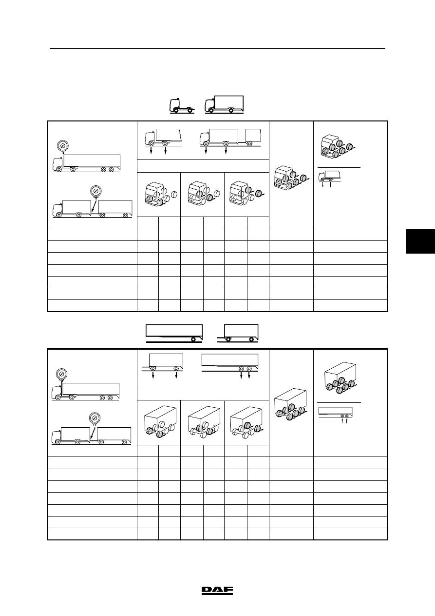
1.4 BRAKE EQUALISATION FORM FOR BRAKE DYNAMOMETER
R600119
R
L
L
R
L
R
0.5
1.0
1.5
2.0
3.0
4.0
5.0
%
%
%
%
%
%
%
R
L
L
R
L
R
0.5
1.0
1.5
2.0
3.0
4.0
5.0
%
%
%
%
%
%
%
p
p
p
p
m 1 + m 2 + . . . . . .
m 1 +
m 2 + . . . . . .
m 1 + m 2 + . . . . . .
m 1 +
m 2 + . . . . . .
R
L
R
L
R
L
R
L
R
L
R
L
F1
F2
F3
F1
F2
F3
F1+F2+F3
m 1 + m 2 + . . . . . .
F1+F2+F3
X 100 %
F1+F2+F3
X 100 %
m 1 + m 2 + . . . . . .
F1+F2+F3

BRAKING PERFORMANCE AND BRAKE EQUALISATION
1-6
©
200436
General
5
ΛΦ45/55 series
6
Filling in brake equalisation form for brake
dynamometer
Note:
1 kg = 10 newtons (N)
1.
Determine the weight of the laden prime
mover and/or trailer vehicle (coupled), and
enter these values in the table (in kg or
newtons).
2.
Make a short test run to warm up the brakes.
3.
Position the vehicle, starting with the front
axle, on a brake dynamometer.
4.
Connect a pressure gauge to the yellow
coupling head.
5.
Depress the brake pedal until the pressure
gauge reading is 0.5 bar.
Always build up pressure, i.e. from low to
high pressure, and never from high pressure
to low pressure, and always begin every
measurement with 0 bar.
6.
Read the braking forces and write them
down in the appropriate column (in kg or
newtons).
7.
Now repeat this procedure at pressures of
1.0 - 1.5 - 2.0 - 3.0 - 4.0 and 5.0 bar.
8.
Also perform these measurements on all
other vehicle axles.
9.
Count all braking forces that belong to a
certain braking pressure and note these in
the "Total braking force" column.
10. Divide the braking forces (in kg or newtons)
just entered at point 9 by the weight of the
vehicle (in kg or newtons), multiply the result
by 100 (%) and enter the values thus
obtained in the next column.
braking deceleration as % of the weight
11. Plot the values obtained in point 10 in the
relevant EC tyre graph.
F
p
R600029
©
200436
1-7
General
BRAKING PERFORMANCE AND BRAKE EQUALISATION
ΛΦ45/55 series
6
5
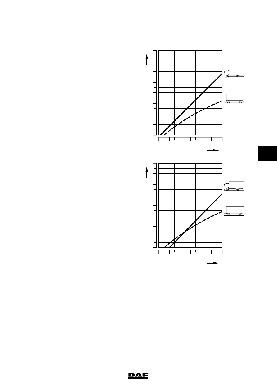
Example of a diagram for a prime mover and
trailer vehicle with poor brake balance.
Example of a diagram for a prime mover and
trailer vehicle with correct brake balance.
The combination is correctly balanced if the
braking performance at 2 - 3 bar for the truck and
the trailer vehicle are in a comparable position in
the appropriate EC band, i.e. both in the upper
part, both in the lower part or both in the middle
part.
%
a
40
30
20
10
0
1
0
2
3
4
5 bar
p
%
a
40
30
20
10
0
1
0
2
3
4
5 bar
p
R600022
BRAKING PERFORMANCE AND BRAKE EQUALISATION
1-8
©
200436
General
5
ΛΦ45/55 series
6
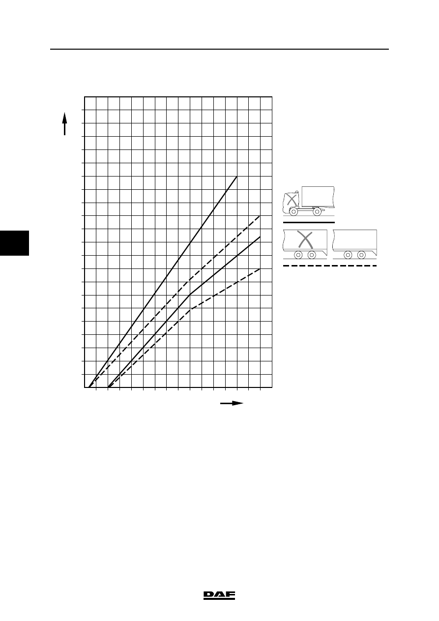
1.5 EC BAND FOR A LADEN TRACTOR/SEMI-TRAILER COMBINATION
The "EC band" indicates the limits within which
the deceleration value must lie.
The "EC band" applies to:
-
tractor with conventional brake system
-
semi-trailer with conventional or EBS brake
system
100
%
a
90
80
70
60
50
40
30
20
10
0
1
0
2
3
4
5
6
7
8
R600881
EBS
EBS
P (bar)
EBS
Нет комментариевНе стесняйтесь поделиться с нами вашим ценным мнением.
Текст