DAF LF45, LF55 Series. Manual — part 267
©
200508
2-3
General
CLUTCH
ΛΦ45/55 series
3
9
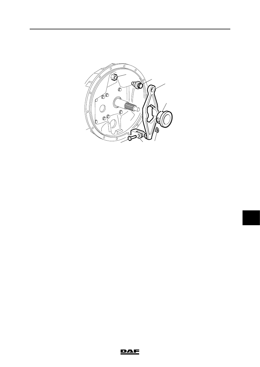
2.3 OVERVIEW DRAWING, CLUTCH LEVER ATTACHMENT TO CLUTCH
HOUSING
V300397
1
2
3
4
6
7
5
1.
Screw adapter
2.
Ball joint
3.
Clutch lever
4.
Thrust bearing
5.
Clip
6.
Claw
7.
Yoke pin
CLUTCH
2-4
©
200508
General
9
ΛΦ45/55 series
3
©
200508
3-1
Description of components
CLUTCH
ΛΦ45/55 series
3
9
3. DESCRIPTION OF COMPONENTS
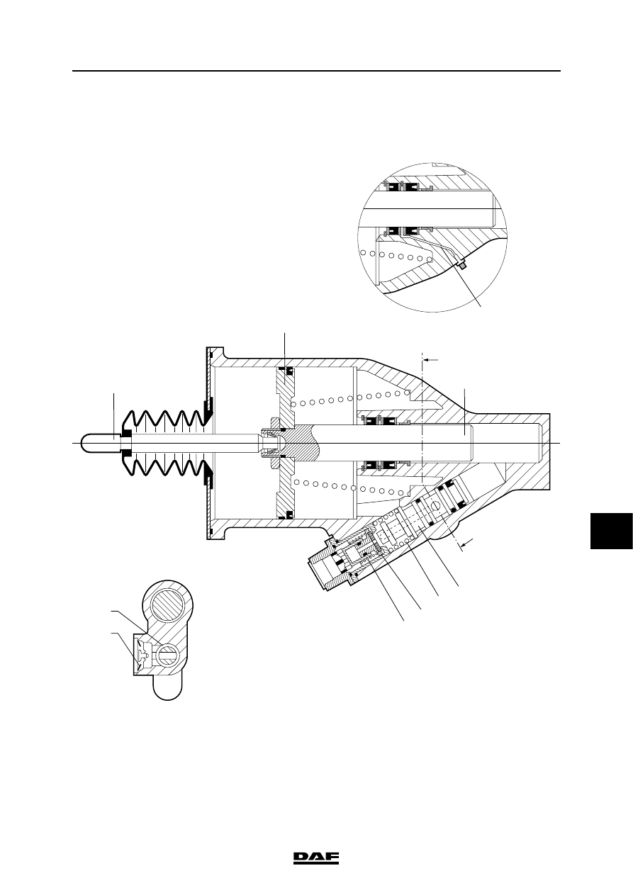
3.1 CLUTCH SERVO
Declutching
Depressing the clutch pedal results in a build-up
of hydraulic pressure.
This causes the servo piston (1) to push the air
valve (2) away from the valve seat, against the
force of the springs (3) and (7).
3
2
7
1
10
8
9
A-A
4
5
6
A
V300352-2
A
CLUTCH
3-2
©
200508
Description of components
9
ΛΦ45/55 series
3
Air pressure now flows into the cylinder.
The pressure pin (4) is pushed forward by the air
pressure building up on air piston (5) and the
hydraulic pressure on fluid piston (6).
The pressure pin (4) pushes against the clutch
lever, which results in declutching.
State of equilibrium
When the hydraulic pressure and pneumatic
support push the pressure pin (4) forwards, a
state of equilibrium is achieved between the air
pressure and the hydraulic pressure (status when
the clutch pedal is not depressed any further).
The servo piston (1) again seals off against the
valve seat, closing the air supply and stopping the
build-up of pneumatic pressure.
Clutching
When the clutch pedal is released, there is no
longer any hydraulic pressure and the servo
piston (1) will be pushed back into its original
position by pressure spring (7) and any remaining
pneumatic support.
As a result, the bleed bore (8) in the servo piston
(1) is no longer closed, and venting takes place
via bleed vent (9).
Vent opening
The function of the vent opening (10) is to prevent
a build up of pressure between both piston seals.
Нет комментариевНе стесняйтесь поделиться с нами вашим ценным мнением.
Текст