DAF LF45, LF55 Series. Manual — part 266
©
200508
1-1
Safety instructions
CLUTCH
ΛΦ45/55 series
3
9
1. SAFETY INSTRUCTIONS
1.1 SAFETY INSTRUCTIONS
Hydraulic fluid is toxic and can
therefore have a damaging effect on
your health. Any direct or indirect
physical contact should therefore be
avoided.
As hydraulic fluid is also corrosive it
may damage the paintwork of the
vehicle. Any contact between
hydraulic fluid and paintwork should
therefore be avoided.
Always use new and clean hydraulic
fluid which has been kept in a sealed
container that meets the
specifications. Hydraulic fluid which
has absorbed water (from the
ambient air) may have an adverse
effect on the operation of the clutch
system. Avoid any contact with
mineral oil. Even one drop of mineral
oil in the system will damage the
seals.
}
}
}
CLUTCH
1-2
©
200508
Safety instructions
9
ΛΦ45/55 series
3
©
200508
2-1
General
CLUTCH
ΛΦ45/55 series
3
9
2. GENERAL
2.1 SYSTEM DESCRIPTION, CLUTCH
The clutch is a single dry-plate clutch which is
hydraulically operated and pneumatically
assisted.
The clutch consists of:
-
flywheel
-
clutch plate
-
clutch release assembly
By clamping the clutch plate between the
flywheel and the clutch release assembly, a
torque can be transferred (by means of friction).
The extent of the torque that can be transferred
by the clutch is determined by multiplying the
maximum engine torque by a safety factor
(usually 1.3).
To clamp the clutch plate, a diaphragm
(pressure) spring is used in the clutch release
assembly.
A diaphragm spring constitutes a simple, strong
and cost-effective construction.
Another advantage of the diaphragm spring is
that the pressure exerted on a new clutch plate
almost equals the pressure exerted on a worn
clutch plate.
A diaphragm spring requires a self-centring thrust
bearing.
The type of clutch plate used depends on the
following factors.
The size of the clutch plate lining must
correspond to the desired service life.
The character of the engine (the engine
vibrations to be damped) determines the version
of the vibration damper design in the hub.
For the clutch plate to engage smoothly the lining
material must abut the flywheel and clutch
release assembly evenly at all places when
engaging.
CLUTCH
2-2
©
200508
General
9
ΛΦ45/55 series
3
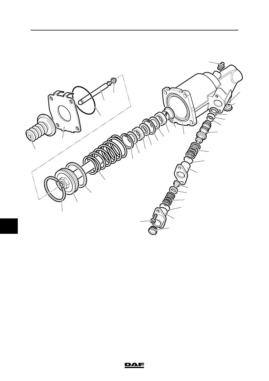
2.2 OVERVIEW DRAWING, CLUTCH SERVO
V3 00 436
17
31
16
19
18
20
21
22
23
24
25
26
27
28
29
30
32
2
1
6
7
8
9
10
11
12
11
10
11
13
14
15
3
4
5
1.
Rubber protective bellows
17.
Vent opening
2.
End-plate
18.
Blow-off nipple
3.
O-ring
19.
Piston seal
4.
Push rod
20.
O-ring
5.
Attachment ring for push rod
21.
O-ring
6.
Split seal
22.
Piston
7.
Piston
23.
Pressure spring
8.
Piston seal
24.
O-ring
9.
Conical spring
25.
Spring seat housing
10.
Circlip
26.
Inlet valve
11.
Washer
27.
Spring seat
12.
Seal, hydraulic part, front
28.
Reset spring
13.
Seal, hydraulic part, rear
29.
O-ring
14.
Split bearing
30.
Connector housing
15.
Booster housing
31.
Allen screw
16.
Bleed nipple
32.
Air filter
Нет комментариевНе стесняйтесь поделиться с нами вашим ценным мнением.
Текст