DAF LF45, LF55 Series. Manual — part 469

©
200436
3-27
Removal and installation
BRAKE SYSTEM AND COMPONENTS
ΛΦ45/55 series
6
4
3.16 REMOVING AND INSTALLING BELLOWS WITH BRAKE CALLIPER THRUST
PIECE, KNORR SB7000 VERSION
Removing bellows with SB7000 brake calliper
thrust piece
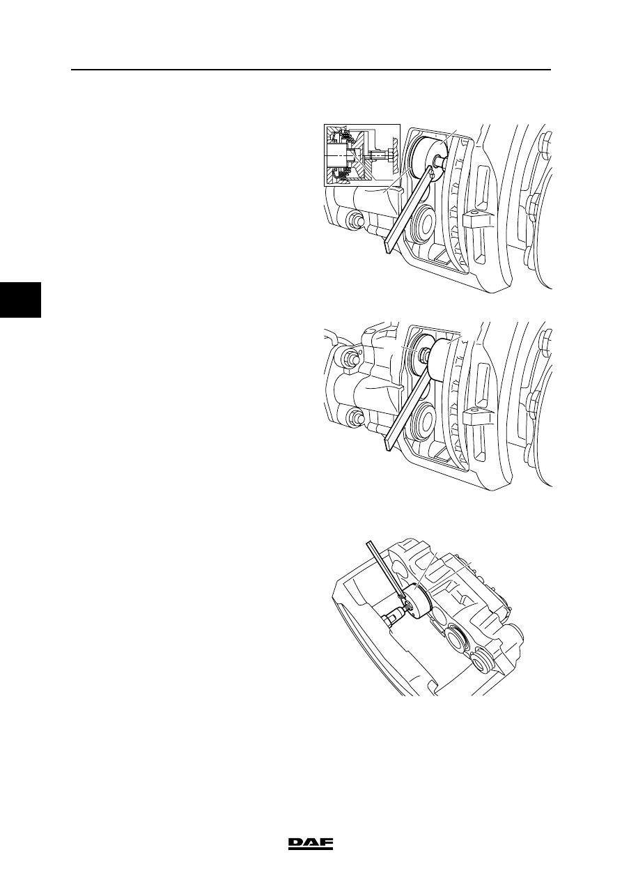
1.
Using the hexagonal adjusting bolt, unscrew
the thrust pieces as far as is necessary to
gain access to the bellows.
Note:
Unscrew the thrust pieces a maximum of
30 mm. Do not screw them completely out of
the brake calliper, as the brake calliper
assembly would then have to be replaced.
Note:
Never turn the hexagonal adjusting bolt
without using an adapter. The adapter is a
torque safety and will break off when the
torque is too high. Without the use of an
adapter the mechanics in the brake calliper
may become damaged when the torque is
too high, so that replacement of the brake
calliper may be necessary.
2.
Using a screwdriver, ease the bellows
behind the thrust piece out of the brake
calliper.
Note:
Do not insert the screwdriver too deeply into
the brake calliper. This could damage the
seat of the inner seal of the thrust pieces.
These cannot be replaced and the brake
calliper would then have to be replaced.
3.
Press the thrust pieces (13) off the adjusters
with the disassembly fork (A), special tool set
(DAF no. 1329494).
4.
Remove the bearing bushes (161) from the
thrust pieces.
R600468
A 13
13
R600469
161
A
BRAKE SYSTEM AND COMPONENTS
3-28
©
200436
Removal and installation
4
ΛΦ45/55 series
6
Fitting bellows
Note:
Do not screw the adjusters entirely out of the
brake calliper, as the entire brake calliper
would then have to be replaced.
1.
Check the screw thread in the adjusters.
2.
Grease the screw thread of the adjusters.
See "Technical data".
3.
Screw the adjusters back into the brake
calliper.
4.
Fit new bearing bushes (161) on the
adjusters.
5.
Fit the thrust pieces and bellows (13) on the
adjusters.
6.
Using the pressure tool and a pin from the
special tool set (DAF no. 1329494) (B),
press the bellows into its seat.
7.
Turn the pressure tool (B) round and press
the thrust pieces (13) onto the adjusters.
Note:
The operations described above can also be
performed if the brake calliper has been
removed. In that case an additional pin (8) from
the special tool set (DAF no. 1329494) must be
used, since the brake disc cannot be used for
support.
B
13
161
R600470
B
13
R600465
B
13
R600464

©
200436
3-29
Removal and installation
BRAKE SYSTEM AND COMPONENTS
ΛΦ45/55 series
6
4
3.17 REMOVING AND INSTALLING BELLOWS WITH BRAKE CALLIPER THRUST
PIECE, KNORR SN7000 VERSION
Removing bellows with SN7000 brake calliper
thrust piece
1.
Using the hexagonal adjusting bolt, unscrew
the thrust pieces as far as is necessary to
gain access to the bellows.
Note:
Unscrew the thrust pieces a maximum of
30 mm. Do not screw them completely out of
the brake calliper, as the brake calliper
assembly would then have to be replaced.
Note:
Never turn the hexagonal adjusting bolt
without using an adapter. The adapter is a
torque safety and will break off when the
torque is too high. Without the use of an
adapter the mechanics in the brake calliper
may become damaged when the torque is
too high, so that replacement of the brake
calliper may be necessary.
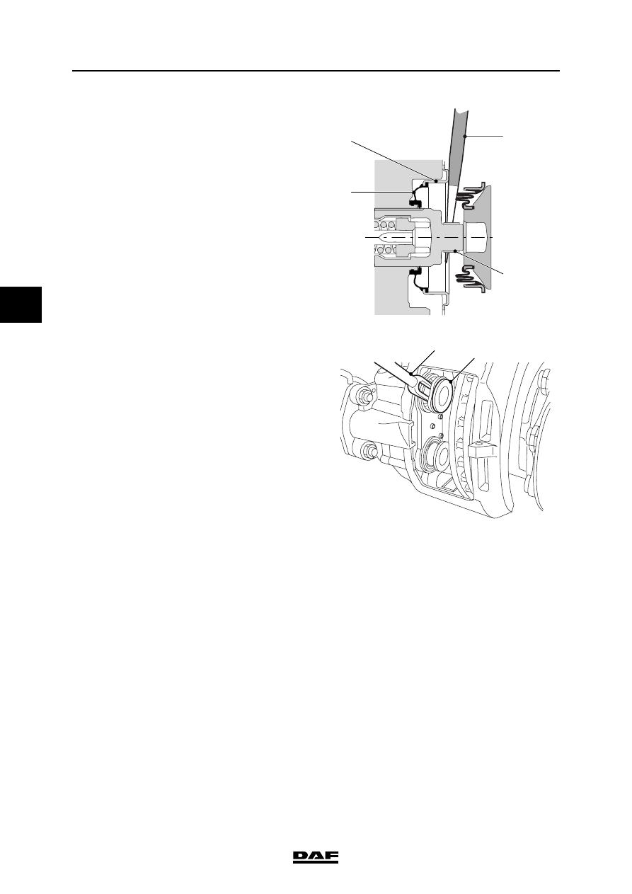
2.
Using a screwdriver (1), ease the bellows
behind the thrust piece (2) out of the brake
calliper.
30 mm
2
2
1
2
R600713
BRAKE SYSTEM AND COMPONENTS
3-30
©
200436
Removal and installation
4
ΛΦ45/55 series
6
Note:
Do not insert the screwdriver (3) too deeply
into the brake calliper. This could damage
the seat (6) of the inner seal (5) of the thrust
pieces. These cannot be replaced and the
brake calliper would then have to be
replaced.
3.
Press the thrust pieces (2) off the adjusters
with the disassembly fork (3), special tool set
(DAF no. 1329495).
4.
Remove the bearing bushes (4) from the
thrust pieces.
Note:
If the bellows of the thrust piece is replaced,
the inner seal must also always be replaced.
5.
Place a brake pad in the brake calliper on the
outside so that the adjusters cannot be
screwed out of the brake calliper at the next
check. Place a 70-mm-thick spacer (self-
made) if the brake calliper has been
removed from the axle.
6.
Screw the adjuster about 30 mm out of the
brake calliper and check the thread of the
adjuster for dirt, corrosion and damage.
7.
Screw the adjuster all the way back into the
brake calliper.
8.
Using a screwdriver, ease the inner seal out
of the brake calliper.
R600714
2
3
3
5
6
4
Нет комментариевНе стесняйтесь поделиться с нами вашим ценным мнением.
Текст