DAF LF45, LF55 Series. Manual — part 468
©
200436
3-23
Removal and installation
BRAKE SYSTEM AND COMPONENTS
ΛΦ45/55 series
6
4
3.14 REMOVAL AND INSTALLATION, BRAKE CALLIPER CARRIER
Removing brake calliper carrier
1.
Remove the brake calliper.
2.
Remove the attachment bolts from the brake
calliper carrier.
3.
Remove the brake calliper carrier.
Fitting the brake calliper carrier
1.
Clean the brake calliper carrier and the
contact surfaces of the stub axle or brake
back plate. Pay particular attention to the
threaded holes and sliding surfaces of the
brake pads.
2.
Fit the brake calliper carrier against the stub
axle or brake back plate.
3.
Fit the attachment bolts and tighten to the
specified torque. See "Technical data".
Note:
Starting in production week 2002-25, the
attachment of the brake calliper against the
stub axle (front axles) may have been
changed on models with disc brakes. Five
bolts are now used instead of six bolts. The
bolt hole for the "6
th
bolt" is then still fitted in
the brake calliper carrier, but not in the stub
axle.
BRAKE SYSTEM AND COMPONENTS
3-24
©
200436
Removal and installation
4
ΛΦ45/55 series
6
3.15 REMOVING AND INSTALLING THRUST PIECE BELLOWS, WABCO MODEL
PAN 17 and PAN 19-1+ versions
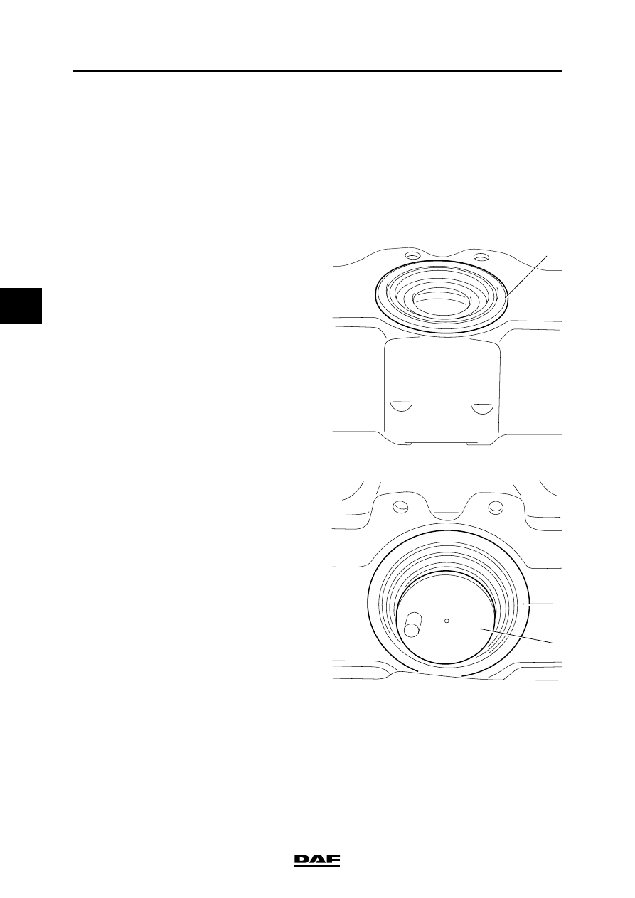
Removing thrust piece bellows
1.
Remove the brake pads and the pressure
plate.
2.
Remove the bellows from the circular slot of
the thrust piece.
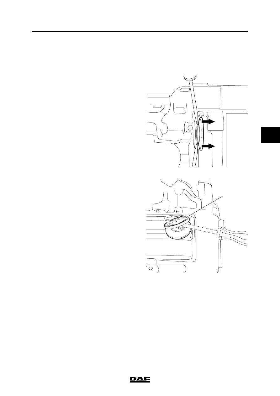
3.
Remove the bellows (1) from the brake
calliper using a screwdriver.
Note:
Unscrew the thrust piece a maximum of
30 mm. Do not screw it completely out of the
brake calliper, as the brake calliper assembly
would then have to be replaced.
Fitting thrust piece bellows
1.
Inspect the screw thread of the adjuster for
corrosion and damage
2.
Apply grease to the screw thread of the
adjuster.
3.
Turn back the adjuster.
4.
Pull the new bellows over the thrust piece.
5.
Push the bellows into the seat of the brake
calliper (2).
6.
Fit the bellows in the seat of the thrust
piece (3).
7.
Fit the pressure plate and the brake pads.
R600586
1
R600587
2
3
©
200436
3-25
Removal and installation
BRAKE SYSTEM AND COMPONENTS
ΛΦ45/55 series
6
4
PAN 19-2 version
Removing thrust piece bellows
1.
Remove the brake pads.
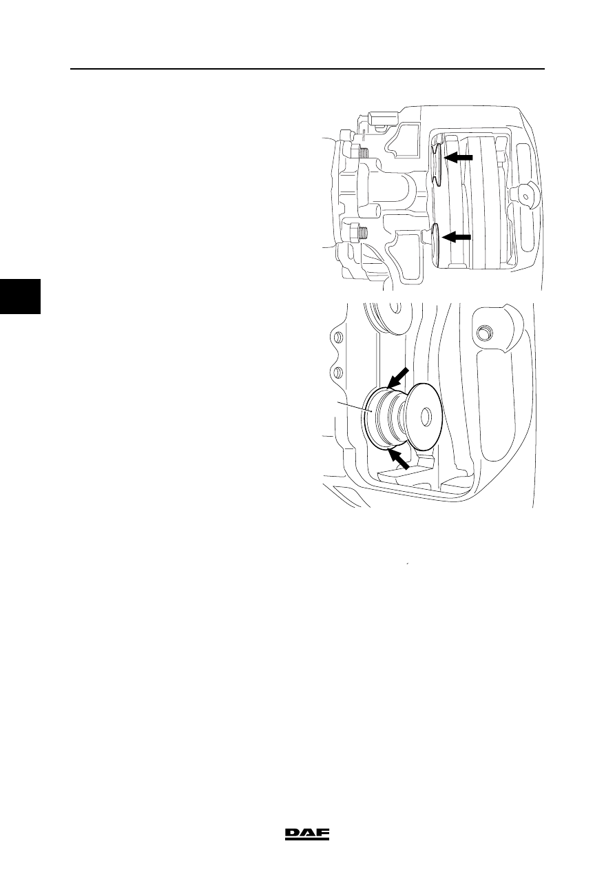
2.
Remove the two thrust pieces from the
adjusting screws, using two screwdrivers
placed at 180
to each other.
3.
Remove the dust covers from the brake
calliper seat using a screwdriver (1).
Note:
Unscrew the thrust pieces a maximum of
30 mm. Do not screw them completely out of
the brake calliper, as the brake calliper
assembly would then have to be replaced.
Fitting thrust piece bellows
1.
Inspect the screw thread of the adjuster for
corrosion and damage
2.
Apply grease to the screw thread of the
adjuster.
3.
Turn back the adjuster.
4.
Position the thrust piece with the bellows in
front of the adjusting screw.
R600583
R600582
1
BRAKE SYSTEM AND COMPONENTS
3-26
©
200436
Removal and installation
4
ΛΦ45/55 series
6
5.
Fit the bellows in the seat of the brake
calliper (2).
6.
Force the thrust piece onto the adjuster.
7.
Fit the brake pads.
R600585
R600584
2
Нет комментариевНе стесняйтесь поделиться с нами вашим ценным мнением.
Текст