DAF LF45, LF55 Series. Manual — part 453
©
200436
2-33
Description of components
OPERATION OF BRAKE COMPONENTS
ΛΦ45/55 series
6
3
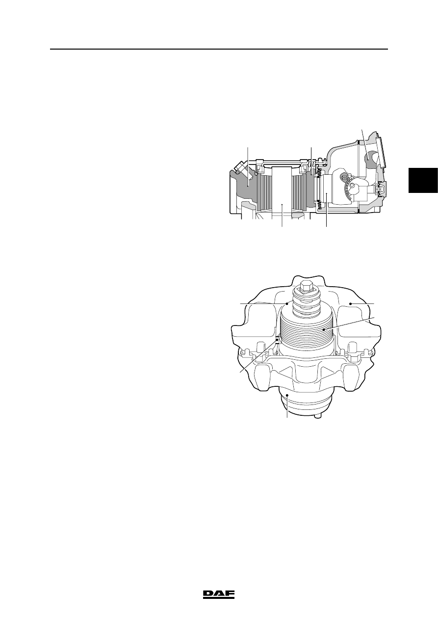
2.18 DISC BRAKE CONSTRUCTION, WABCO MODEL
PAN 17 and PAN 19-1+ versions
Operation
Brakes
This disc brake operates using a pneumatic
brake cylinder or spring brake cylinder.
If the brake is applied, the brake cylinder push
rod presses against the eccentrically mounted
lever (1).
Via brake cylinder 2 and pressure plate 3, the
brake pad is pressed against the inside of the
brake disc (4).
Due to the reaction force at the eccentric, the
floating brake calliper (5) will also press the
opposite brake pad with the same force.
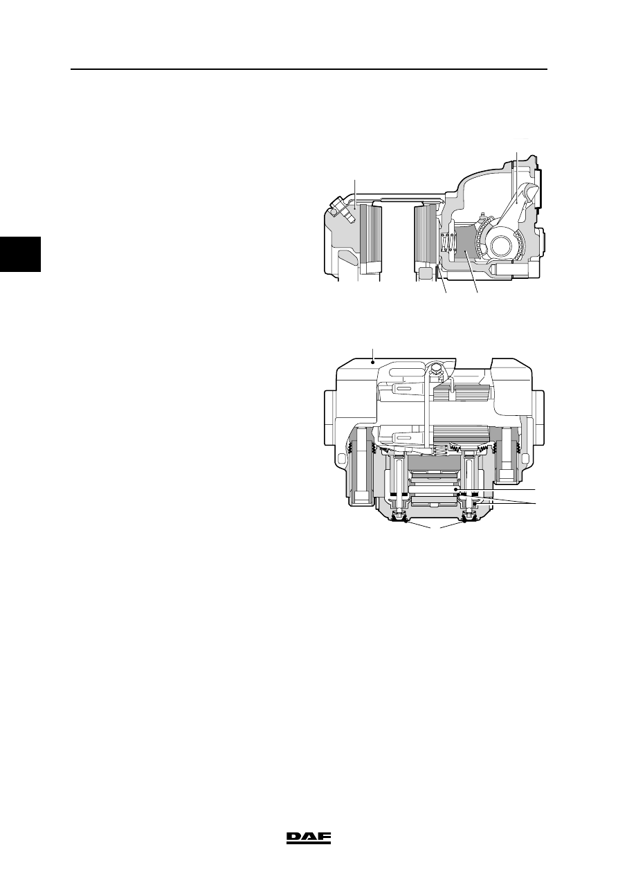
Adjusting
If the eccentrically mounted lever (6) is operated
by the push rod of the brake cylinder, the pin (7)
on the lever will rotate the adjuster (8) and the
pressure cylinder (9) in the outgoing stroke until
the play has been eliminated.
If the brake is no longer being operated, the
lever (6) will turn the adjuster (8) back in the
opposite direction. The spring (10) in the adjuster
will ensure that the pressure cylinder will hardly
rotate. The result is that a small total play of about
0.5 mm will remain between the brake pads and
brake disc.
Brake pad wear wires
Brake pad wear wires are fitted to the brake pads.
These wires are cut through when the brake
lining has been worn down to the minimum
thickness.
This is the signal for the VIC system to activate
the "brake pad wear" warning symbol on DIP-4.
R600573
R600574
1
3
5
4
2
R600579
9
7
8
6
10
OPERATION OF BRAKE COMPONENTS
2-34
©
200436
Description of components
3
ΛΦ45/55 series
6
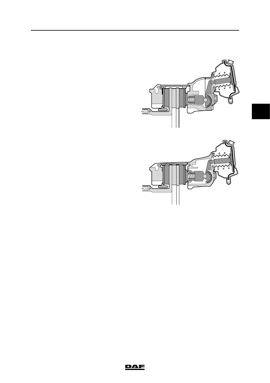
PAN 19-2 version
Operation
Brakes
This disc brake operates using a pneumatic
brake cylinder or spring brake cylinder.
If the brake is applied, the brake cylinder push
rod presses against the eccentrically mounted
lever (1).
The brake pad is forced against the inside of the
brake disc via the brake piston (2) and the
pressure plate (3).
Due to the reaction force at the eccentric, the
floating brake calliper (4) will also press the
opposite brake pad with the same force.
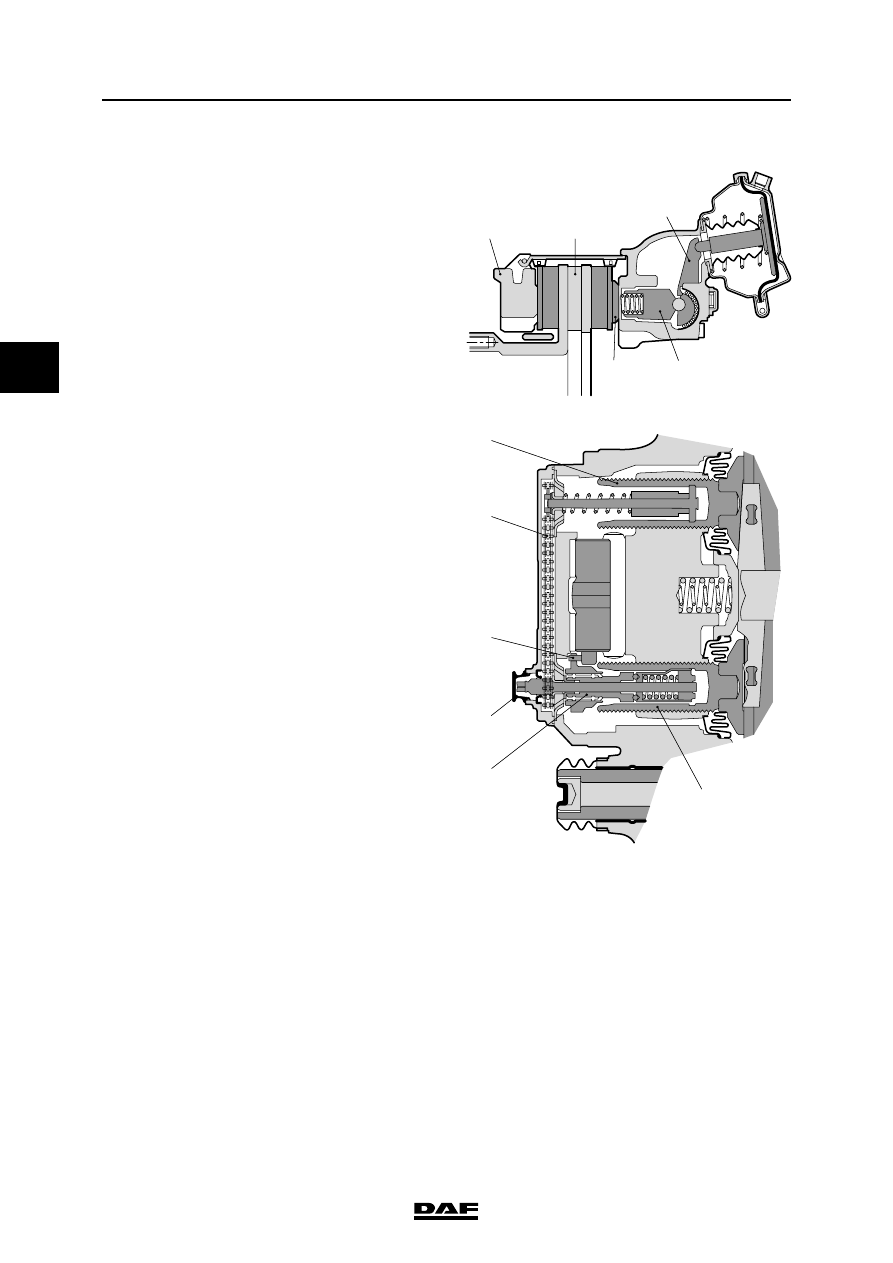
Adjusting
This adjuster and the eccentric are equipped with
teeth (6) that engage each other.
If the play is too great, the adjuster (7) will be
rotated by these teeth the next time the brakes
are applied, so that the play will be reduced.
Under normal conditions, the adjuster will push
against the brake pad before rotation can take
place. However, if rotation does take place, it will
be absorbed by a slip coupling.
By removing one of the rubber caps (8) where the
automatic adjuster is located, a hexagon is
revealed. Using a ring spanner, the play can be
manually set by adjusting this hexagon.
Brake pad wear wires
Brake pad wear wires are fitted to the brake pads.
These wires are cut through when the brake
lining has been worn down to the minimum
thickness.
This is the signal for the VIC system to activate
the "brake pad wear" warning symbol on the
instrument panel.
R600578
3
4
1
2
R600577
6
7
8
5
©
200436
2-35
Description of components
OPERATION OF BRAKE COMPONENTS
ΛΦ45/55 series
6
3
2.19 DISC BRAKE CONSTRUCTION, KNORR MODEL
The disc brake construction consists of the brake
disc and the brake calliper. There are two
variants of this construction:
-
Knorr SB7000, recognisable by the divided
housing between the brake cylinder and the
brake pad holder.
-
Knorr SN7000, recognisable by the
undivided housing between the brake
cylinder and the brake pad holder.
The operation of the two variants is identical.
Only the reconditioning of the brake calliper is
different.
The Knorr SB7000 construction has been used
since the introduction of the LF 45/55 series. The
Knorr SN7000 construction is used in production
from week 41-2002 on all front axles and on air-
sprung rear axles (Class 3 vehicles). On leaf-
sprung rear axles the Knorr SB7000 construction
is still used. The operation of the two variants is
identical. Only overhauling and the parts of the
brake calliper differ.
Operation
Brakes
This disc brake operates using a pneumatic
brake cylinder or spring brake cylinder.
If the brake is applied, the brake cylinder push
rod presses against the eccentrically mounted
lever (1).
Via the bridge (2) and the threaded bushes (3),
the brake pad is pressed against the brake
disc (4) at two points on the inside.
Due to the reaction force at the eccentric, the
floating brake calliper (5) will also press the
opposite brake pad with the same force.
R600707
SB7000
SN7000
OPERATION OF BRAKE COMPONENTS
2-36
©
200436
Description of components
3
ΛΦ45/55 series
6
Adjusting
One of the two threaded bushes (3) is equipped
with the mechanics for automatic adjustment of
the play between the brake pads and brake disc.
This adjuster and the eccentric are equipped with
teeth (6) that engage each other.
If the play is too great, the adjuster (8) will be
rotated by these teeth the next time the brakes
are applied, so that the play will be reduced.
Under normal conditions, the adjuster will push
against the brake pad before rotation can take
place. However, if rotation does take place, it will
be absorbed by a slip coupling.
The rotation of the adjuster is transferred by
means of a chain (7) to the other adjuster.
By removing a rubber cap (9) where the
automatic adjuster is located, a hexagon is
revealed. Using a ring spanner, the play can be
manually set by adjusting this hexagon.
4
5
1
3
2
R600486
R600487
3
7
6
8
3
9
Нет комментариевНе стесняйтесь поделиться с нами вашим ценным мнением.
Текст