DAF LF45, LF55 Series. Manual — part 451
©
200436
2-25
Description of components
OPERATION OF BRAKE COMPONENTS
ΛΦ45/55 series
6
3
PARKING BRAKE VALVE WITHOUT TRAILER
VEHICLE CONNECTION
Purpose
The parking brake valve enables controlled
operation of the parking brake system of the
prime mover.
Operation
The parking brake valve has 2 positions:
-
driving
-
parking
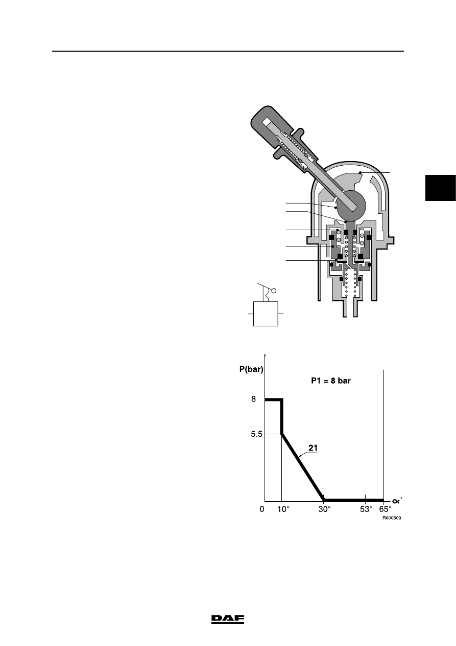
Driving
With the handle in the driving position, there is a
through-connection of the supply pressure
(connecting point 1) to connecting point 2 for the
spring brake cylinders. The bleed vent is now
closed.
The output pressure at connecting point 2 is now
approx. 8 bar (see graph).
Emergency braking
If the handle is pulled a little backwards against
the spring pressure, tappet 3 will move
downwards via the eccentric (2). The space at
connecting point 21 can now be bled and as a
result the pressure at connecting point 21 will
drop. Spring 4 forces piston 5 down until valve 6
comes into contact with the seal collar of tappet
3. A state of equilibrium has now been achieved.
When the handle is moved against stop 7, the
bleed vent will remain open so that the spring
brakes are applied to maximum effect (max.
emergency brake position).
R600400
2
7
3
4
5
6
1
3
2
1
2
OPERATION OF BRAKE COMPONENTS
2-26
©
200436
Description of components
3
ΛΦ45/55 series
6
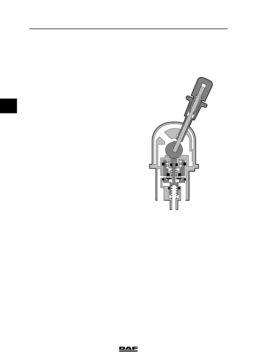
Parking
When the handle is pulled past stop 7, it is locked
in position.
Connecting point 2 is still pressureless, so that
the spring brakes operate at maximum capacity.
Releasing the brakes
When the handle is once again moved fully
forwards, tappet 3 will move upwards, seat
against valve 6 and push it from its seat in piston
5. As a result, the supply pressure can reach
connection point 2. The pressure at connecting
point 2 is now once more equal to the supply
pressure at connecting point 1.
3
2
1
R600402
©
200436
2-27
Description of components
OPERATION OF BRAKE COMPONENTS
ΛΦ45/55 series
6
3
2.15 SPRING BRAKE CYLINDER
Purpose
The purpose of the spring brake cylinder is to
force the brake pads against the brake disc when
the service or parking brake is operated.
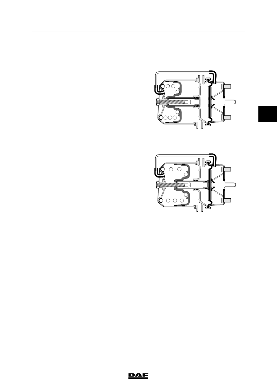
Spring brake cylinder operation
The spring brake cylinder consists of two parts: a
part for the service brake, which is designed as a
normal brake cylinder, and a part for the parking
brake, which is a spring brake cylinder.
Normal position during driving.
The air reservoirs must be at a safe pressure
before you start driving. If this is not the case, a
warning signal (e.g. a buzzer) will be given.
If this pressure is admitted to the spring brake
cylinder, the piston will compress the powerful
spring. The push rod is no longer under load and
the vehicle brake will be released due to the
operation of the spring, etc.
Service brake
Because the brake cylinder and the spring brake
cylinder are separate, the spring brake cannot
affect the operation of the service brake.
When the service brake is applied, the powerful
spring continues to be compressed, while there is
air pressure on the diaphragm of the brake
cylinder. When the foot brake valve is operated,
the compressed air passes through connection
point 11 into the chamber behind the diaphragm.
The diaphragm with push rod is pushed out
against the spring pressure.
The air on the other side of the diaphragm can
escape via bleed holes. When the brakes are
released, the spring forces the push rod and the
diaphragm back into their original position.
11
12
R600908
11
12
R600909
OPERATION OF BRAKE COMPONENTS
2-28
©
200436
Description of components
3
ΛΦ45/55 series
6
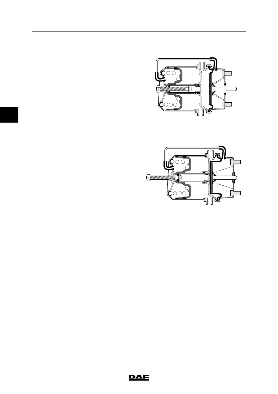
Parking brake
Connection point 12 is bled.
The powerful spring then forces the piston with
the piston tube against the diaphragm, so that the
push rod is forced outwards. Here use is made of
the continuously available energy of the
compressed, powerful spring.
Release tool, spring brake cylinder with
unscrewable release bolt
If, due to a failure, no compressed air is available
in the spring brake cylinder, the vehicle brakes
are automatically applied.
But it must still be possible to tow the vehicle.
The spring brake cylinder is therefore fitted with a
release bolt at the rear. By turning this bolt anti-
clockwise using a spanner, the powerful spring
will be compressed.
As the bolt is provided with a thrust bearing, the
torque required is not more than 20 - 40 Nm.
A pneumatic spanner must not be used for this
purpose.
Because the spring brakes have
been released mechanically, the
parking brake can no longer be
applied.
Once the failure has been remedied and
sufficient compressed air is available, the control
valve can be used to again admit air into the
spring brake cylinder.
The release bolt should then be screwed back in
with the spanner and tightened to the specified
torque. See "Technical data". The pressure in the
spring brake cylinder circuit should be at least
5.1 bar.
11
12
R600908
11
12
R600910
}
Нет комментариевНе стесняйтесь поделиться с нами вашим ценным мнением.
Текст