DAF LF45, LF55 Series. Manual — part 385
1
1427090/03
EL001557
54
55
56
57
58
59
60
61
62
63
64
65
66
67
68
69
70
71
72
73
74
75
76
77
78
79
80
81
82
83
84
85
86
87
88
89
90
91
92
93
94
95
96
97
98
99
100
101
102
103
104
105
106
1000
1000
1000
1000
1008
4176
3173
1167
1127
1167
BN
BW
BN
BW
1167
1167
1008
1167
1167
1167
4179
1167
4178
4178
4176
9036
4176
4174
4174
4175
4174
4175
4174
4175
4175
1009
1009
1167
1167
4176
9036
4176
4177
4177
4177
4177
4176
4179
4179
1123
9303
1123
9303
9001
4179
4179
1357
4179
1357
1357
1357
1357
1357
4178
A500
1/705
2/705
B525
A1/
752
A5/
752
D900
E1/
747
E349
80A
2
1
A3
718
4
822
A1
718
3
822
7
822
3
834
5
822
E330
5A
2
1
E153
10A
2
1
G367
88
88A
85A
85B
86
G368
88
88A
85A
85B
86
C853
5
71
0I
C854
1
2
!
!
!
!
!
!
!
!
!
!
!
A5
A7
C2
C5
C4
A2
C1
A3
A4
A1
D924
G425
30
85
86
87A
87
2
822
1
834
2
834
2
832
1
832
6
822
8
822
1
833
2
833
D826
+
4
2
3
1
831
4
902
2
831
3
A513
3
B6/702
D942
1000
1000
1010
1010
E143
10A
200440
2-29
5
ELECTRICAL SYSTEM
Electrical system
series
45/55
LF
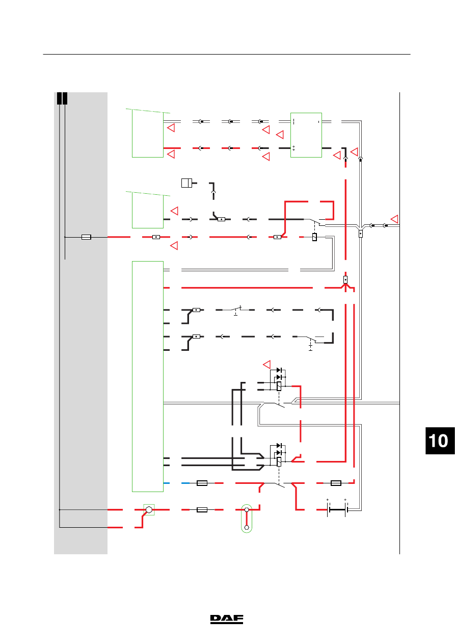
2.
IGNITION/ST
ARTER
SWITCH/CHARGING
C
IRCUIT
CONT
ACT
CIRCUIT
When
ignition/starter
switch
C
841
is
turned
to
the
“accessories”
position
(contact
1
connected
to
contact
6),
the
“accessories”
relay
(G355)
is
energised
via
wire
1130.
If
ignition
switch
C841
is
turned
further
(contact
1
is
connected
to
4),
ignition
relay
G015
will
be
activated
via
wire
4001.
Wire
1010
is
supplied
w
ith
power
.
ST
ARTING
C
IRCUIT
When
the
contact
switch
is
turned
to
the
“start”
position,
contacts1
and
2
in
this
switch
are
connected.
Power
is
supplied
to
relay
G203
via
w
ire
4002.
The
V
IC
(D900)
connects
G203
to
earth
when
the
neutral
position
switch
(E569)
in
the
gearbox
is
closed.
Relay
G203
now
supplies
power
via
w
ire
4009
to
connection
point
50
of
the
starter
motor
(B010).
A
s
a
result,
the
starter
m
otor
is
energised. This
means
that
if
the
gearbox
is
not
in
neutral
the
V
IC
does
not
connect
relay
G203
to
earth
and
the
relay
is
therefore
not
energised.
CHARGING
C
IRCUIT
When
the
ignition
is
switched
on,
power
is
supplied
to
both
the
B+
connection
and
connection
15
(pin
3)
of
the
alternator
.
An
internal
resistor
in
the
alternator
is
energised
by
an
IC
in
the
carbon
brush
holder
.
This
resistor
ensures
that
a
low
level
of
current
passes
through
the
energising
resistor
.T
his
excites
a
magnetic
field
in
the
alternator
.
After
starting,
the
voltage
on
terminals
B
+
and
15
(pin
3)
will
rise
to
about
28.5
V.
O
nce
this
voltage
is
reached,
the
control
IC
in
the
regulator
interrupts
the
pre-exciter
coil
to
enable
the
voltage
to
be
regulated.
The
magnetic
field
w
ill
now
disappear
,s
o
that
the
generator
will
not
be
energised
for
a
short
period
of
time.
As
a
result,
the
voltage
on
outputs
B
+
and
15
will
drop.
The
regulator
reactivates
w
hen
the
voltage
drops
below
27.6
V.
T
his
m
eans
that
the
voltage
supplied
by
the
generator
remains
relatively
constant.
T
he
batteries
are
supplied
through
generator
output
B+1.
The
alternator
charging
current
warning
lamp
is
activated
via
wire
1020,
which
is
connected
to
the
V
IC
(D900).
T
he
VIC
controls
the
D
IP
via
the
CAN
network.
T
he
voltage
on
wire
1020
is
switched
by
the
control
IC.
Errors
are
also
shown
on
the
DIP
display
through
this
connection.
The
alternator
is
also
equipped
with
a
‘sens’
connection
(pin
4).
H
owever
,t
his
connection
is
not
used
and
is
now
connected
directly
to
B+2.
The
function
of
this
connection
is
to
correct
the
voltage
dif
ference
between
B+
and
the
batteries.
200440
2-30
5
ELECTRICAL SYSTEM
Electrical system
series
45/55
LF

2
1427090/03
EL001559
1
2
3
4
5
6
7
8
9
10
11
12
13
14
15
16
17
18
19
20
21
22
23
24
25
26
27
28
29
30
31
32
33
34
35
36
37
38
39
40
41
42
43
44
45
46
47
48
49
50
51
52
53
1000
4009
4002
1000
4002
1000
4173
1211
4001
1000
1000
1000
1000
1000
1000
1211
1020
4009
1000
4009
1211
1020
4721
1211
1020
1020
4721
4721
1211
G014
1
5
1000
1000
1000
1130
4001
1211
A500
50
30
B010
M
31
1
730
5
768
4
720
B3
714
3
858
8
720
1/705
2/705
1/704
B12/702
B8/703
A5/701
A11/702
A10/702
G525
G525
4
768
2
858
B1
718
C51/
745
D900
D29/
746
C20/
745
D903
B39/
757
E349
80A
2
1
E286
125A
2
1
D942
1000
1010
4173
4001
G203
32
1
4
G015
3
1
24
M
1010
1000
E035
10A
G355
1
18
C841
1/808
2/808
4/808
6/808
E569
2
4
G
3
B+1
L /2
B-
+15 /3
S /4
A513
B+2
G520
200440
2-31
5
ELECTRICAL SYSTEM
Electrical system
series
45/55
LF

3.
TACHOGRAPH
SEE
THE
SYSTEM
MANUAL
FOR
M
ORE
INFORMA
T
ION
Location 19
Electronic
unit,
ECAS-3
(D851):
If
ECAS-2
fitted,
then
electronic
unit
D
802
200440
2-32
5
ELECTRICAL SYSTEM
Electrical system
series
45/55
LF
Нет комментариевНе стесняйтесь поделиться с нами вашим ценным мнением.
Текст