DAF LF45, LF55 Series. Manual — part 466
©
200436
3-15
Removal and installation
BRAKE SYSTEM AND COMPONENTS
ΛΦ45/55 series
6
4
3.9 REMOVAL AND INSTALLATION, BRAKE DISC, WABCO MODEL
Removal, brake disc
1.
Remove the wheel.
2.
Remove the brake calliper from the axle.
3.
Remove the hub from the axle.
4.
Loosen the Allen screws of the brake disc.
5.
Remove the brake disc from the hub.
Installation, brake disc
1.
Clean the contact surfaces between the hub
and the brake disc.
2.
Fit the brake disc on the hub.
3.
Fit the Allen screws and tighten them to the
specified torque. See "Technical data".
4.
Fit the hub and brake disc on the axle.
5.
Fit the brake calliper.
BRAKE SYSTEM AND COMPONENTS
3-16
©
200436
Removal and installation
4
ΛΦ45/55 series
6
3.10 REMOVAL AND INSTALLATION, BRAKE DISC, KNORR MODEL
Removal, brake disc
1.
Remove the hub.
2.
Remove the locking plates.
3.
Remove the spring plates between the disc
and hub and tap the disc off the hub using a
copper hammer.
If the disc does not come free from the hub,
it can be removed by placing it on an old
brake drum and pushing it off the hub using
a press.
Installation, brake disc
1.
Remove dirt and corrosion from the contact
surfaces of the brake disc and hub.
2.
Position the brake disc on the hub.
3.
Fit the spring plates and tighten them to the
specified torque. See "Technical data".
©
200436
3-17
Removal and installation
BRAKE SYSTEM AND COMPONENTS
ΛΦ45/55 series
6
4
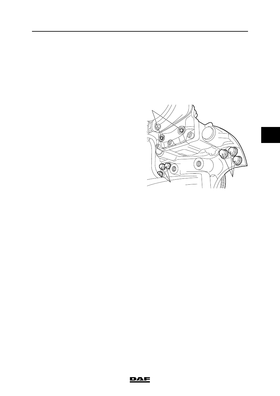
3.11 REMOVAL AND INSTALLATION, BRAKE CALLIPER, WABCO MODEL
Removing the brake calliper
1.
Remove the plug for the brake pad wear
indicator.
2.
Remove the brake pads.
3.
Remove the brake cylinder.
4.
Remove the attachment bolts (8) from the
brake calliper.
5.
Remove the brake calliper from the axle.
Installing the brake calliper
1.
Place the brake calliper on the axle.
2.
Turn the attachment bolts into the brake
calliper and tighten them to the specified
torque. See "Technical data".
Note:
Tighten the attachment bolts in the specified
sequence. See "Technical data".
3.
Fit the brake cylinder.
4.
Fit the brake pads.
5.
Fit the plug for the brake pad wear indicator.
R600572
9
8
8

BRAKE SYSTEM AND COMPONENTS
3-18
©
200436
Removal and installation
4
ΛΦ45/55 series
6
3.12 REMOVAL AND INSTALLATION, BRAKE CALLIPER, KNORR SB7000
VERSION
Never insert fingers between the
brake calliper and the brake calliper
carrier during and following removal
of the brake pads and when a new
brake calliper is installed (danger of
getting them trapped). Always take
hold of the brake calliper on the
outside.
Removing the brake calliper
1.
Remove the brake pads.
2.
Remove the brake cylinder.
3.
Remove the plug for the brake pad wear
indicator.
4.
Remove the clamping strap (31) and the
rubber bellows (10).
5.
Remove the Allen screws (2 and 3).
6.
Remove the brake calliper.
Fitting the brake calliper
1.
Clean all parts and check for damage. The
sliding surfaces of moving parts must be
clean and undamaged.
2.
Position the brake calliper on the brake
calliper carrier.
}
31
39
R600466
10
40
2
3
R600720
Нет комментариевНе стесняйтесь поделиться с нами вашим ценным мнением.
Текст