DAF LF45, LF55 Series. Manual — part 449

©
200436
2-17
Description of components
OPERATION OF BRAKE COMPONENTS
ΛΦ45/55 series
6
3
Reducing pressure at connecting point 2
By activating the magnet coil (9), the solenoid
valve (11) will open bore 15 and close bore 22. As
a result, input pressure enters space 15 above
diaphragm 5 via a bore. Diaphragm 5 seals
against seat 7, so that no more pressure can
build up.
By activating the magnet coil (10) at the same
time, bore 16 opens and bore 23 closes.
By opening bore 16, the pressure under
diaphragm 6 can be reduced via the bleed vent.
The pressure in the brake chamber can now
escape via connecting point 2, space 20 and an
internal bore to the bleed vent.
6
19
20
16
7
5
10
22
11
15
9
12
4
23
2
1
R600630
P (bar)
t (sec)
2

OPERATION OF BRAKE COMPONENTS
2-18
©
200436
Description of components
3
ΛΦ45/55 series
6
Maintaining pressure at connecting point 2
By deactivating the magnet coil (10), the input
pressure can be guided through a bore past the
magnet coil (10) into space 19 under diaphragm
6, thus sealing off diaphragm 6.
The pressure in the brake chamber can now no
longer be guided to the bleed vent via space 20.
This keeps the pressure in the brake chamber
constant.
R600631
2
1
6
20
19
16
10
12
23
P (bar)
t (sec)
2
©
200436
2-19
Description of components
OPERATION OF BRAKE COMPONENTS
ΛΦ45/55 series
6
3
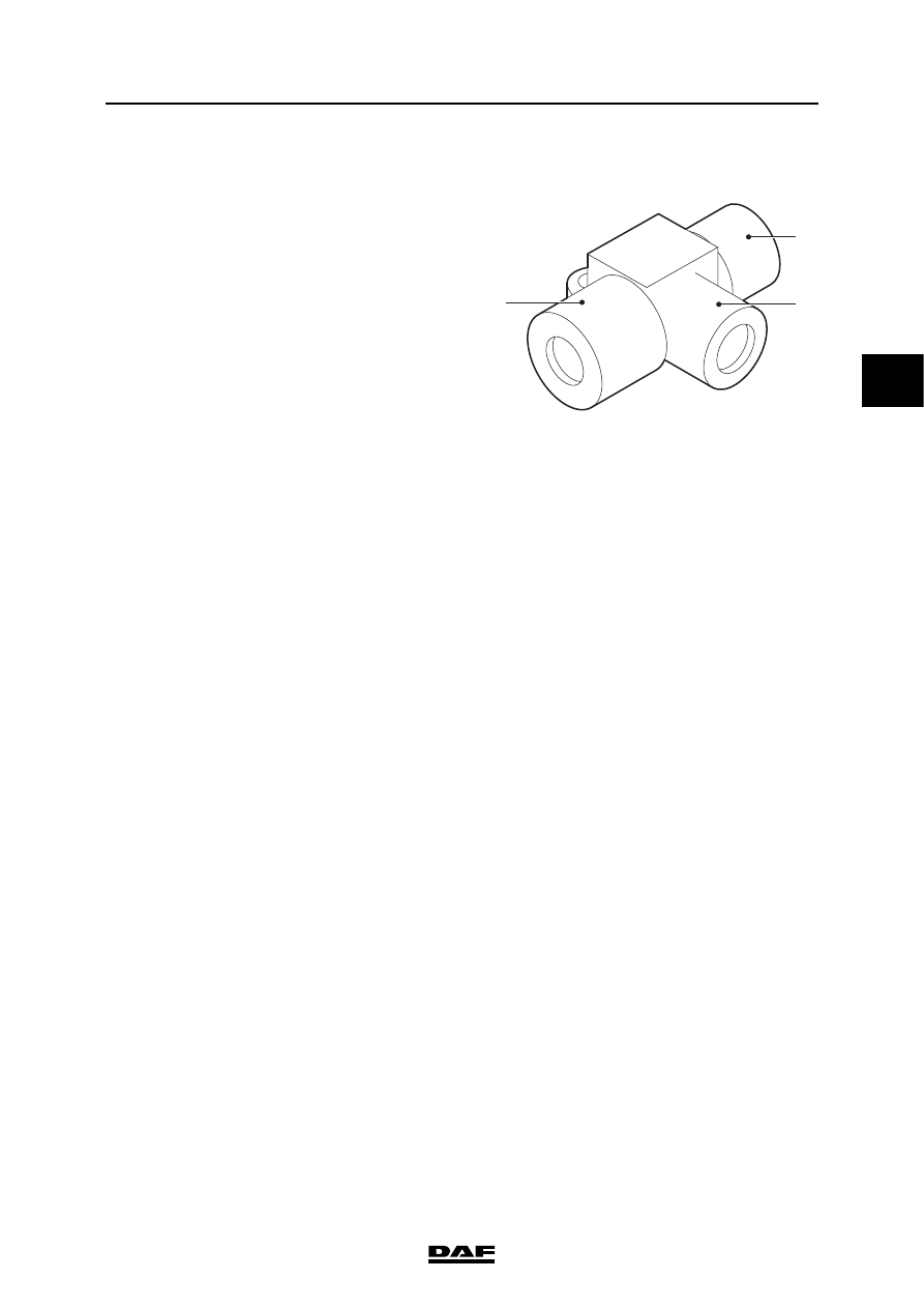
2.10 TWO-WAY VALVE
This valve is used in drum brakes as a double
check valve, that is to say a safety measure so
that the maximum service brake and parking
brake cannot operate the wheel brakes at the
same time.
Purpose
The purpose of this valve is to let through
unchanged the highest of two submitted pressure
signals.
Operation
When pressure is applied to one of the entrances
or if the pressure on one entrance is higher than
on the other, the little piston will shut off the other
entrance and the air can leave the valve
unhindered again via the exit.
No connection can be established between the
two entrances.
11
21
12
R600747

OPERATION OF BRAKE COMPONENTS
2-20
©
200436
Description of components
3
ΛΦ45/55 series
6
2.11 ASR SOLENOID VALVE
The ASR valve serves to transfer brake pressure
to the ABS valve during an ASR differential brake
control. Depending on the slip, the ABS valve will
control the brake pressure to the respective brake
chamber.
The ASR valve is a simple electropneumatic
valve, which is normally closed, that transfers air
pressure when it is electrically energised.
The energising is controlled by the ABS/ASR
electronic unit.
Note:
The bleed vent (3) must always point downwards.
If coil E of the ASR valve is energised, core B will
move down against the pressure of spring F.
Seal A will now open connecting point 1, so that
supply pressure can leave the valve via
connecting point 2. Opening C and therefore
bleed vent 3 are also closed as core B moves
downwards.
When coil E is no longer energised, core B will
move upward under the influence of spring F.
This action will close connecting point 1 and open
opening C. Connecting point 2 is now linked to
bleed vent 3.
R600601
2
3
C
B
D
E
F
A
1
4
Нет комментариевНе стесняйтесь поделиться с нами вашим ценным мнением.
Текст