DAF LF45, LF55 Series. Manual — part 450
©
200436
2-21
Description of components
OPERATION OF BRAKE COMPONENTS
ΛΦ45/55 series
6
3
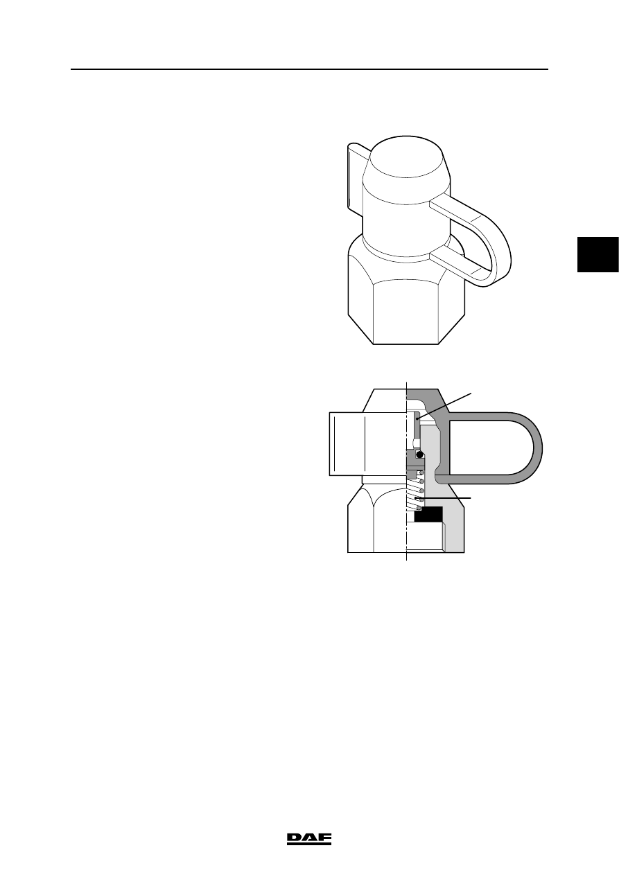
2.12 EMERGENCY FILLING/TEST CONNECTION
In various places in the brake system there are
test connections for carrying out inspections and
adjustments. A pipe leads from point 24 of the air
dryer to the rear left of the cab. There is a test
connection here that can be used as an
emergency/tyre filling connection.
Note:
With a leaf-spring front axle this test connection is
on point 11 of the air dryer.
If a pipe is connected to the test connection,
screwing in the union will lift the spring-loaded
valve (A) from its seat, opening the supply. If the
union is removed, the valve is pushed onto its
seat by spring B, closing the supply.
A
B
R600495

OPERATION OF BRAKE COMPONENTS
2-22
©
200436
Description of components
3
ΛΦ45/55 series
6
2.13 BRAKE CYLINDER
Purpose
The purpose of the brake cylinder is to apply the
brake shoes or pads to the brake drum/disc.
Operation
When the foot brake valve is operated,
compressed air is admitted at the pressure side
of the diaphragm (1). The diaphragm (1) and
push rod (2) are pushed outwards against the
pressure of the spring. As a result, the brake
shoes are forced against the brake drum via a
lever mechanism. The air on the other side of the
diaphragm can escape via bleed holes and the
clearance around the push rod.
When the brakes are released, the coil spring (3)
will force the push rod and the diaphragm back to
their initial position.
When the brakes are released, the brake cylinder
will always draw in outside air on the non-
pressure side. When the brakes are released the
push rod should return fully to its initial position.
The actuating pressure should not exceed
0.5 bar.
R600505
2
1
3
R600506
©
200436
2-23
Description of components
OPERATION OF BRAKE COMPONENTS
ΛΦ45/55 series
6
3
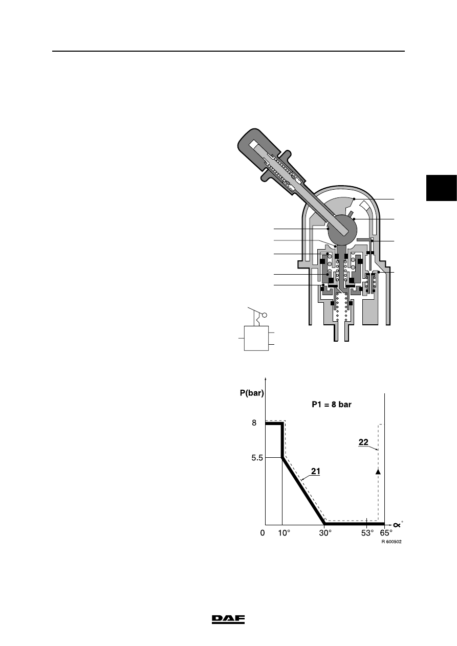
2.14 PARKING BRAKE VALVE
PARKING BRAKE VALVE WITH TRAILER
VEHICLE CONNECTION
Purpose
The parking brake valve enables simultaneous,
controlled operation of both the parking brake
system of the prime mover and the trailer brakes.
Operation
The parking brake valve has 3 positions:
-
driving
-
parking
-
test
Driving
With the handle in the driving position, there is a
through-connection in the valve of the supply
pressure (connecting point 1) to the connecting
points for the spring-brake cylinders (21) and the
trailer (22). The bleed vent is now closed.
The output pressure at connection points 21 and
22 is now approx. 8 bar (see graph).
3
21
1
22
2
3
5
4
6
8
7
9
10
R600397
1
21
22
OPERATION OF BRAKE COMPONENTS
2-24
©
200436
Description of components
3
ΛΦ45/55 series
6
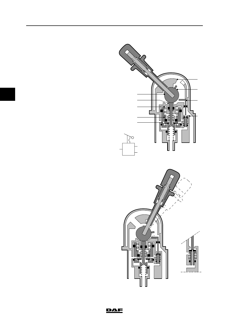
Emergency braking
If the handle is pulled a little backwards against
the spring pressure, tappet 3 will move
downwards via the eccentric (2). The space at
connecting point 21 can now be bled and as a
result the pressure at connecting point 21 will
drop. Via the bore in valve 10 the pressure at
connection point 22 will also drop. Spring 4 forces
piston 5 down until valve 6 comes into contact
with the seal collar of tappet 3. A state of
equilibrium has now been achieved.
When the handle is moved against stop 7, the
bleed vent will remain open, so that the spring
brakes and the trailer brakes will be applied to
their maximum (max. emergency-brake position).
Parking
When the handle is pulled past stop 7, it is locked
in position.
Connection points 21 and 22 will remain
pressureless, so that the spring brakes and the
trailer brakes are still applied to their maximum.
Test
When the handle is moved beyond the parking
position, cam 8 will move tappet 9 downwards,
causing the bore in valve 10 to be closed and this
valve to be lifted from its seat.
The supply pressure can now be passed to
connection point 22 via a bore in piston 5. As a
result, the trailer brakes will be released.
Connection point 21 remains bled, so that the
spring brakes keep the parking brake applied.
The combination is now braked only by the force
exerted by the spring-brake cylinders on the
tractor. It can now be checked whether the
combination remains motionless when the trailer
vehicle brakes are not applied. When the handle
is released, it will automatically return to the
parking position.
Releasing the brakes
When the handle is once again moved fully
forwards, tappet 3 will move upwards, seat
against valve 6 and push it from its seat in piston
5. As a result, the pressure can reach connection
points 21 and 22.
3
21
1
22
2
3
5
4
6
8
7
9
10
R600397
1
21
22
3
21
1
22
R600399
Нет комментариевНе стесняйтесь поделиться с нами вашим ценным мнением.
Текст