DAF LF45, LF55 Series. Manual — part 448
©
200436
2-13
Description of components
OPERATION OF BRAKE COMPONENTS
ΛΦ45/55 series
6
3
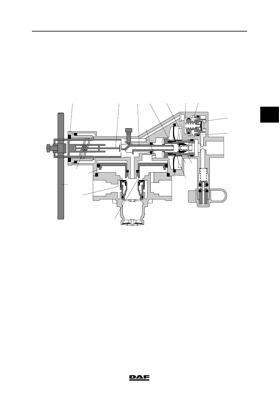
2.8 LOAD SENSING VALVE, LEAF SUSPENSION
Purpose
Automatic control of the brake force depends on
the deflection of the springs and therefore on the
loading condition of the vehicle. Thanks to the
integrated relay valve, the brake cylinders are
aerated and bled quickly.
Operation
The control valve is attached to the chassis and
connected to the rear axle by means of a rod.
With unladen vehicles, the distance between the
regulator and the axle is largest and the lever (j)
points fully downwards. When the vehicle is
loaded, this distance decreases and the lever
moves upwards, towards full load position.
Pin i rotates at the same time as the lever and as
a result thereof moves to the right via the control
groove in bearing cover p. Rod "q" brings the
tappet (g) in a position that corresponds with the
loading condition.
The compressed air provided by the foot brake
valve flows via connecting point 4 into space A,
pushing piston b to the left. Outlet "d" is closed
and inlet "m" is opened, causing compressed air
to enter space C to the left of diaphragm "e".
Relay piston "f" is operated via duct F and
chamber G.
3
2
1
4
E
C
C
F
D
A
G
B
a
n
o
m
d
g
q
j
i
f
e
l
k
p
h
c b
R600456
OPERATION OF BRAKE COMPONENTS
2-14
©
200436
Description of components
3
ΛΦ45/55 series
6
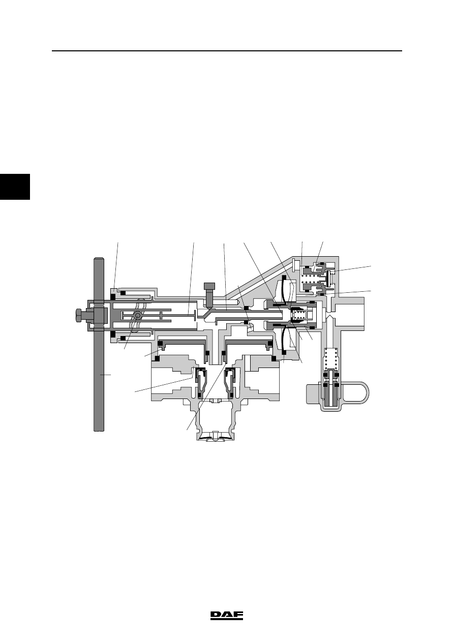
At the same time, compressed air flows through
the open valve (a) and duct E into space D to the
right of diaphragm "e". Due to this control, the
output pressure at partial load and low control
pressures is increased (to max. 1.4 bar). If the
control pressure increases further, piston "n" is
moved to the left against the pressure of spring
"o" and valve "a" closes.
As pressure builds up in space G, relay piston "f"
is pressed downwards. Outlet "h" closes and inlet
"k" opens. The air at connecting point 1 now flows
to the brake cylinders via connecting point 2.
Now pressure will start to build up in space B
under relay piston "f". As soon as this pressure is
somewhat higher than that in space G, the piston
is pushed upwards and closes inlet "k".
When piston "b" is moved to the left, the vanes (l)
attached to it will gradually loosen the diaphragm
(e) from the fixed vanes in the fan housing. As a
result, the effective diaphragm surface will
gradually increase. As soon as the force of the air
to the left of the diaphragm exceeds that to the
right, piston "b" will move to the right. The inlet
(m) will be closed and a set position is reached.
The position of the tappet (g), which is dependent
on the position of lever "j", is indicative of the
effective diaphragm surface and therefore of the
output brake pressure.
3
2
1
4
E
C
C
F
D
A
G
B
a
n
o
m
d
g
q
j
i
f
e
l
k
p
h
c b
R600456
©
200436
2-15
Description of components
OPERATION OF BRAKE COMPONENTS
ΛΦ45/55 series
6
3
The position of the tappet (g) determines to what
extent piston "b" must be moved with the vane
disc (l) to allow the valve to build up pressure.
Due to this movement, the effective surface of the
diaphragm will alter.
In full-load position, this surface and that of piston
"b" are equally large. The control pressure at
connecting point 4 is therefore let through
(ratio 1:1) to spaces C and G. The output
pressure at 2 will now be equal to the control
pressure at connecting point 4.
If the pressure decreases at connecting point 4,
piston "b" will be pushed to the right by the
pressure in space C. Bleed vent d will open and
the pressure in spaces C and G will fall. The relay
piston will be pushed up due to the pressure still
present in space B, causing bleed vent "h" to
open. The pressure at connecting point 2 will now
fall via bleed vent 3.
A stop bolt in front of the tappet (g) ensures that
this valve can always provide the minimum brake
pressure if lever "j" is in too low a position due to
a fault. The factory setting of this bolt must not be
changed.

OPERATION OF BRAKE COMPONENTS
2-16
©
200436
Description of components
3
ΛΦ45/55 series
6
2.9 ABS VALVE
The ABS valve must keep the pressure constant
in the brake chamber during an ABS control, or
decrease the pressure in the brake chamber
regardless of the pressure leaving the foot brake
valve.
If the ABS valve is not operative, it has no
function and the input pressure at connecting
point 1 is the same as the output pressure at
connecting point 2 to the brake chamber.
Increasing pressure at connecting point 2
Input pressure at connecting point 1 coming from
the foot brake valve will lift diaphragm 5 from
seat 7, causing the brake pressure to be guided
to the brake chamber via connecting point 2.
The input pressure will also be guided through a
bore past the magnet coil (10) in space 19 under
diaphragm 6, causing diaphragm 6 to form a seal
on seat 8. Connecting point 2 is thus sealed off
from the bleed vent.
1
2
R600264
6
8
19
10
7
5
2
1
R600629
P (bar)
t (sec)
2
Нет комментариевНе стесняйтесь поделиться с нами вашим ценным мнением.
Текст