DAF LF45, LF55 Series. Manual — part 305
©
200416
4-3
Removal and installation
BE ENGINE INLET/EXHAUST SYSTEM
ΛΦ45/55 series
4
3
13. Fit the exhaust pipe to the turbocharger.
14. Fit the charge pipes to the exhaust pipe.
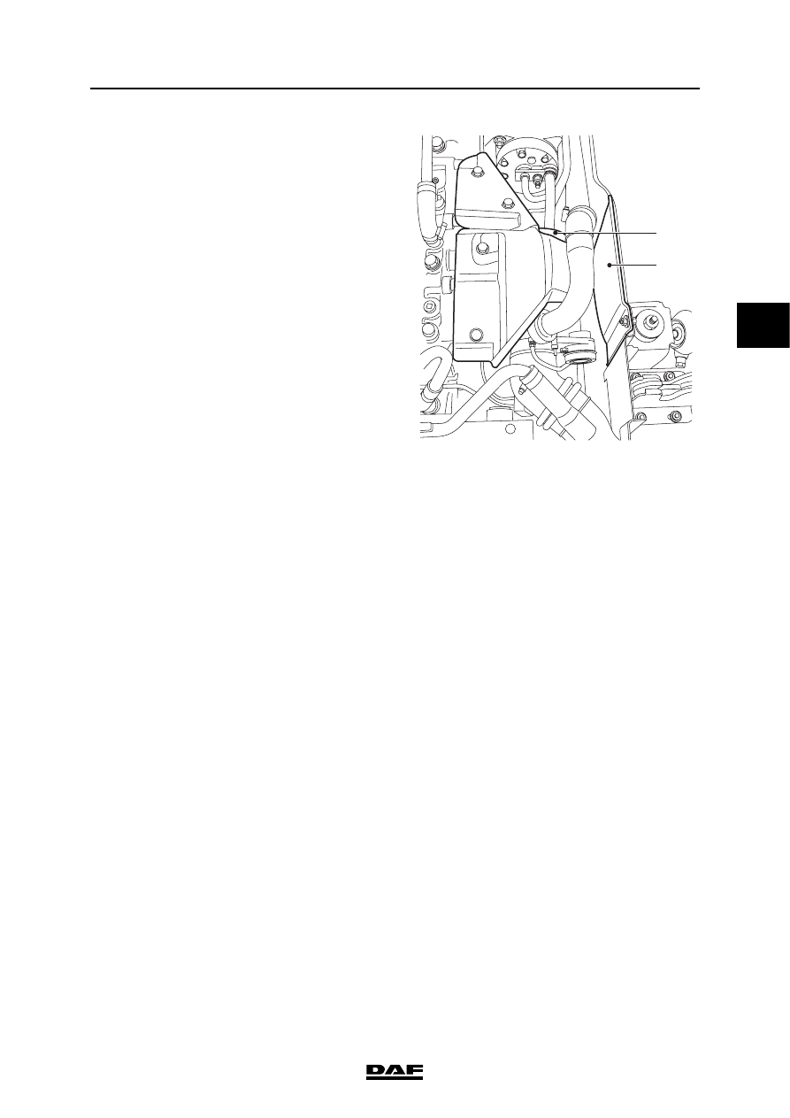
15. Fit the heat shield (1) to the oil filter.
16. Install the engine encapsulation (2).
1
i400857
2
BE ENGINE INLET/EXHAUST SYSTEM
4-4
©
200416
Removal and installation
3
ΛΦ45/55 series
4
4.2 REMOVAL AND INSTALLATION OF AIR COOLER
Removing the air cooler
1.
Disconnect the earth lead from the battery
terminal.
2.
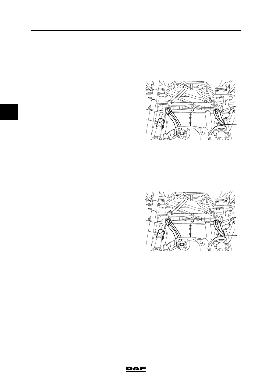
If the vehicle has air conditioning, loosen the
support of the refrigerant pipes (2) on the
radiator and remove the condenser from the
air cooler supports.
3.
Loosen the support of the coolant pipes (1)
on the radiator.
4.
Remove the charge pipes (3) from the air
cooler and plug the openings.
5.
Disconnect the air cooler.
6.
Remove the air cooler.
Installing the air cooler
1.
Clean the outside of the air cooler with
compressed air.
2.
Install the air cooler and tighten the air cooler
attachments.
3.
Fit the charge pipes (3) to the air cooler.
4.
Fit the bracket of the coolant pipes (1) on the
radiator.
5.
If the vehicle has air conditioning, fit the
condenser in the air cooler supports and
tighten the support of the refrigerant pipes
(2) on the radiator.
6.
Connect the battery terminals.
7.
Start the engine and check for leakage.
i400822
2
3
1
3
i400822
2
3
1
3
©
200416
4-5
Removal and installation
BE ENGINE INLET/EXHAUST SYSTEM
ΛΦ45/55 series
4
3
4.3 REMOVAL AND INSTALLATION, AIR FILTER ELEMENT
Removing the air filter element
1.
Loosen all clamping brackets on the air filter
cover.
2.
Remove the air filter cover.
3.
Remove the air filter element.
4.
Clean the inside of the air filter housing and
the air filter cover.
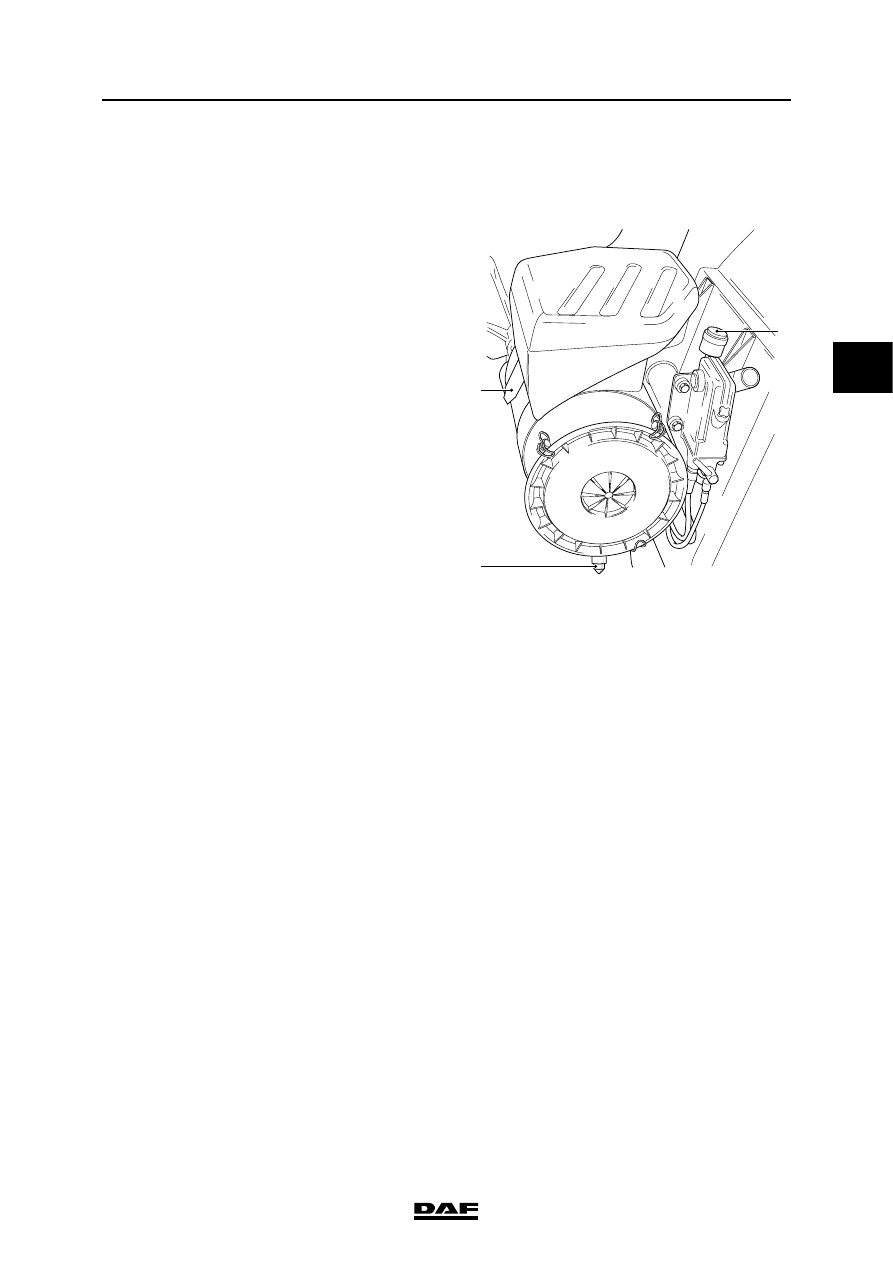
5.
Clean the rubber sealing valves (1 and 2) on
the filter housing. Check the sealing valve for
damage.
Installing the air filter element
1.
Fit the air filter element in the air filter
housing.
2.
Fit the air filter cover.
3.
Install all the clamping brackets.
4.
Reset the air filter indicator (3) by pressing
the knob on the indicator.
I4 00 535
3
1
2
BE ENGINE INLET/EXHAUST SYSTEM
4-6
©
200416
Removal and installation
3
ΛΦ45/55 series
4
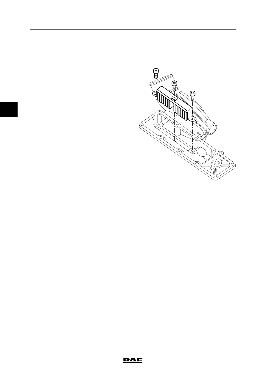
4.4 REMOVAL AND INSTALLATION, GLOW PLUG
Removing the glow plug
1.
Remove the inlet manifold.
2.
Remove the attachment bolts from the glow
plug and remove the glow plug.
Installing the glow plug
1.
Fit the glow plug and tighten the attachment
bolts to the specified torque. See "Technical
data".
2.
Fit the inlet manifold.
M201155
Нет комментариевНе стесняйтесь поделиться с нами вашим ценным мнением.
Текст