DAF LF45, LF55 Series. Manual — part 655

©
200515
4-11
Removal and installation
EXPLANATORY NOTES ON THE MAINTENANCE ACTIVITIES
ΛΦ45/55 series
5
4.10 REMOVAL AND INSTALLATION, F36/F48 FRONT AXLE WHEEL HUB
Removing the hub
1.
Support the front axle in a safe manner.
2.
Remove the wheel.
3.
Remove the wheel speed sensor (1).
4.
Remove the cap placed over the adjusting
bolt (1). Reset the brake pads by unscrewing
the adjusting bolt (1) clockwise as far as it will
go.
5.
Remove the attachment bolts (3) from the
brake calliper (2). Remove the brake calliper
(2) with attached pipes from the stub axle.
Put the brake calliper (2) aside.
1
S7 00 589
R600559
1
2
3
3
EXPLANATORY NOTES ON THE MAINTENANCE ACTIVITIES
4-12
©
200515
Removal and installation
5
ΛΦ45/55 series
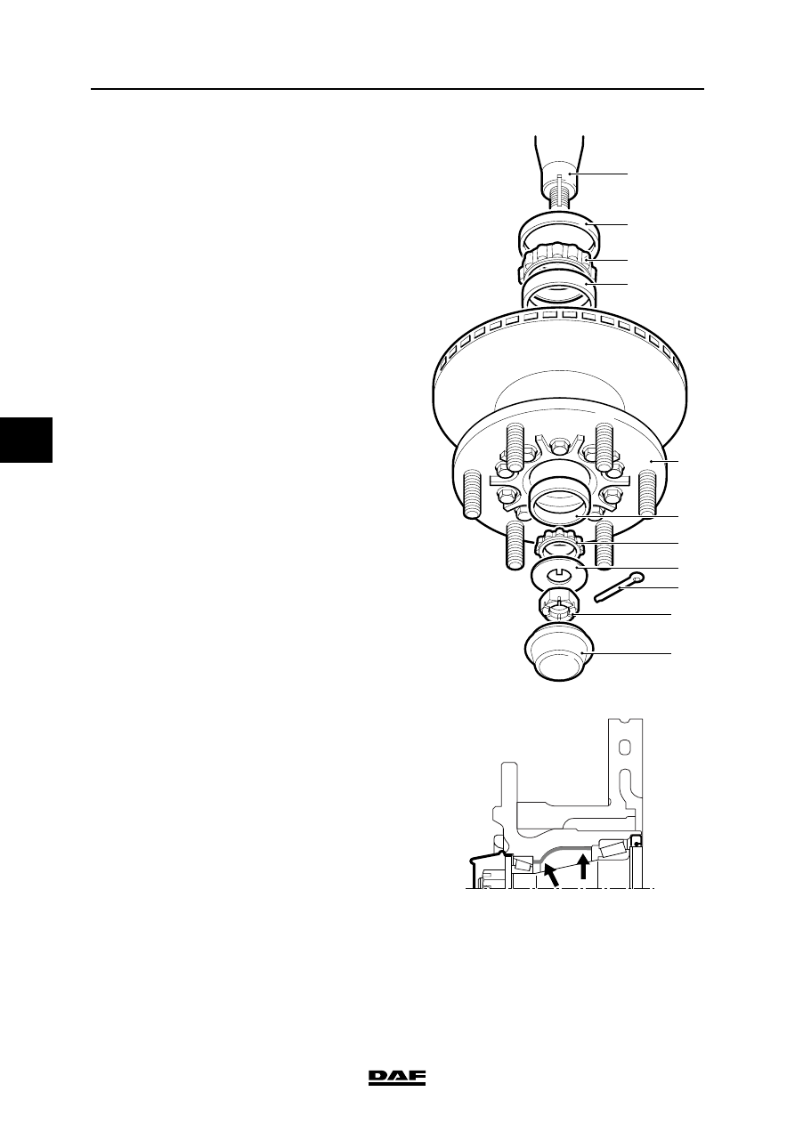
6.
Remove the hub cap (11).
7.
Remove the lock nut (10).
8.
Remove the hub (5) from the axle journal (1).
Save the circlip (8) and the bearing cage (7).
9.
Remove the seal (2) from the hub (5).
10. Take the bearing cage (3) out of the hub (5).
Installing the hub
1.
Clean the axle journal (1) and check for
damage.
2.
Clean the bearing cages (3) and (7).
3.
Remove the grease from the hub (5) and
clean the ball races (4) and (6).
4.
Check the bearing cages (3) and (7) and the
ball races (4) and (6) for wear and damage.
If necessary, fit new wheel bearings.
5.
Apply an ample quantity of the specified
grease to the bearing cages (3) and (7).
6.
Fit the bearing cage (3) into the hub (5).
7.
Apply a layer of grease (approx. 6 mm thick)
to the hub cavity.
1
2
3
4
5
6
7
8
9
10
11
S7 00 573
;;;;
;;;;
;;;;
;;;;
;;
;;
;;;
;;;;
;;;;
;;;;
;;;;
;;
;;
S7 00 572
©
200515
4-13
Removal and installation
EXPLANATORY NOTES ON THE MAINTENANCE ACTIVITIES
ΛΦ45/55 series
5
8.
Fit a new seal (2) in the hub (5).
9.
Fit the hub (5) to the axle journal (1).
10. Fit the bearing cage (7).
11. Apply the specified grease to the front of the
bearing cage (7).
12. Install the circlip (8).
13. Fit the lock nut (10). Tighten the lock nut (10)
to the specified torque. See "Technical data".
Rotate the hub (1), while securing the lock
nut (10), to allow the bearings to set.
14. Turn the lock nut (10) back through
approximately 90
. It should be possible to fit
the split pin (9).
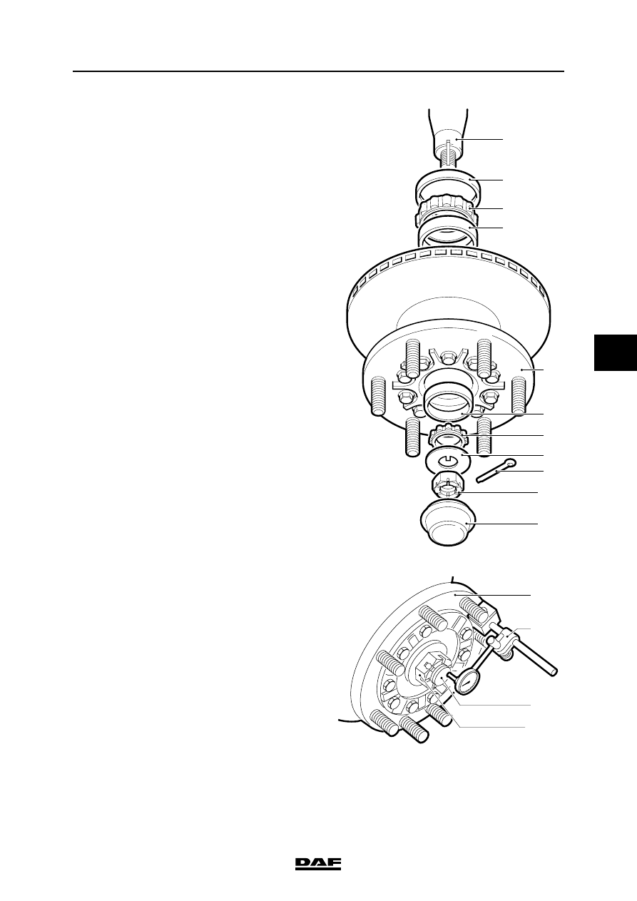
15. Place a micrometer (A) on the wheel hub (5).
Allow the stylus to rest on the end of the axle
journal (1).
16. Push and pull on the wheel hub (5). Check
the wheel bearing play and compare this with
the specified value. See "Technical data".
17. If necessary, correct the wheel bearing play
by tightening or loosening the lock nut (10).
18. Fit a new split pin (9) in the lock nut (10).
19. Fit the hub cap (11). Attention: the hub cap
must not be filled with grease.
1
2
3
4
5
6
7
8
9
10
11
S7 00 573
5
1
A
10
S7 00 574

EXPLANATORY NOTES ON THE MAINTENANCE ACTIVITIES
4-14
©
200515
Removal and installation
5
ΛΦ45/55 series
20. Apply locking compound to the attachment
bolts (3) of the brake calliper (2). See
"Technical data".
21. Install the brake calliper (2). Tighten the
attachment bolts (3) in the specified
sequence to the specified torque. See
"Technical data".
22. Set the brake pad clearance. To do this, turn
the adjusting bolt (1) anti-clockwise until the
brake pads abut the brake disc. Then turn
the adjusting bolt (1) clockwise through 90
.
Check that the brake disc runs freely.
23. Fit the cap on the adjusting bolt (1).
24. Install the wheel speed sensor (1) and press
it against the sensor ring. The required
clearance will be produced while on the
move.
25. Fit the wheel.
R600559
1
2
3
3
1
S7 00 589
Нет комментариевНе стесняйтесь поделиться с нами вашим ценным мнением.
Текст