DAF LF45, LF55 Series. Manual — part 648
©
200515
3-21
Inspection and adjustment
EXPLANATORY NOTES ON THE MAINTENANCE ACTIVITIES
ΛΦ45/55 series
5
3.26 INSPECTION AND ADJUSTMENT, LOAD SENSING VALVE, LEAF
SUSPENSION
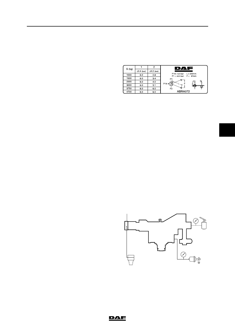
Explanatory notes on instruction plate
The data relating to axle loads and output
pressures are listed on the instruction plate
following the sequence of the axles beneath the
vehicle.
"1" refers to the (first) front axle, "2" to the
following axle, etc.
In the entire column, a reading of 6 bar has been
filled in under "1". If the vehicle is equipped with
an empty/load valve, a pressure ratio is entered
in the box under the valve illustration, e.g. "i = 1 :
1,5". The "output pressure P2" of axle 1 will give
variable readings.
These values can be used to check the brake
pressure values of the front axle and to carry out
the inspection/adjustment below at the same
time. To do this, connect a pressure gauge to the
test connection of one of the front axle brake
cylinders.
Inspection/adjustment
1.
Measure the weight plus load of the rear
axle.
2.
Check the attachment of the control lever
and its ease of operation.
3.
Check that the right type of valve has been
fitted.
4.
Check the length of the control lever
(see "L" on the instruction plate).
5.
Connect a pressure gauge (4) to the test
connection near connection 1/4 on the load
sensing valve (input pressure).
6.
Connect pressure gauge (2) to the test
connection on one of the brake cylinders
(service brake connection) of the rear axle.
7.
Make sure that the reservoir pressure is
higher than 6.5 bar throughout the testing
process.
8.
Depress the brake pedal until pressure
gauge (4) indicates a value of 6 bar.
9.
Read the brake pressure of the rear axle
from pressure gauge 2 and check that this
value matches the one listed on the
instruction plate in the table under "output
pressure p2" to the rear axle.
R6 00 549
1/4
4
2
2
R600562
1

EXPLANATORY NOTES ON THE MAINTENANCE ACTIVITIES
3-22
©
200515
Inspection and adjustment
5
ΛΦ45/55 series
10. If necessary, correct the brake pressure by
adjusting the length of the vertical
connecting rod (2). Never attempt to alter the
length L of the (horizontal) control lever.
11. Remove the ball coupling (1) and raise the
control lever. Check that the output pressure
is now allowed through (almost) without
reduction.
Note:
The small socket head screw in the centre of
the valve must not be adjusted.
Drive and chassis
1
2
R6 00 568
L
©
200515
3-23
Inspection and adjustment
EXPLANATORY NOTES ON THE MAINTENANCE ACTIVITIES
ΛΦ45/55 series
5
3.27 CHECKING THE DIFFERENTIAL FOR LEAKS
1.
Visually inspect the differential for leaks.
3.28 CHECKING THE OPERATION OF THE DIFFERENTIAL LOCK
1.
Jack up the rear axle and support the axle on
stands.
2.
Bring the air system to operating pressure.
3.
Engage the differential lock. The warning
indicator should now be active.
4.
Check that there is a "rigid" connection
between the driven wheels.
5.
Disengage the differential lock. The warning
light should now go out and the "rigid"
connection between the driven wheels
should be broken.
EXPLANATORY NOTES ON THE MAINTENANCE ACTIVITIES
3-24
©
200515
Inspection and adjustment
5
ΛΦ45/55 series
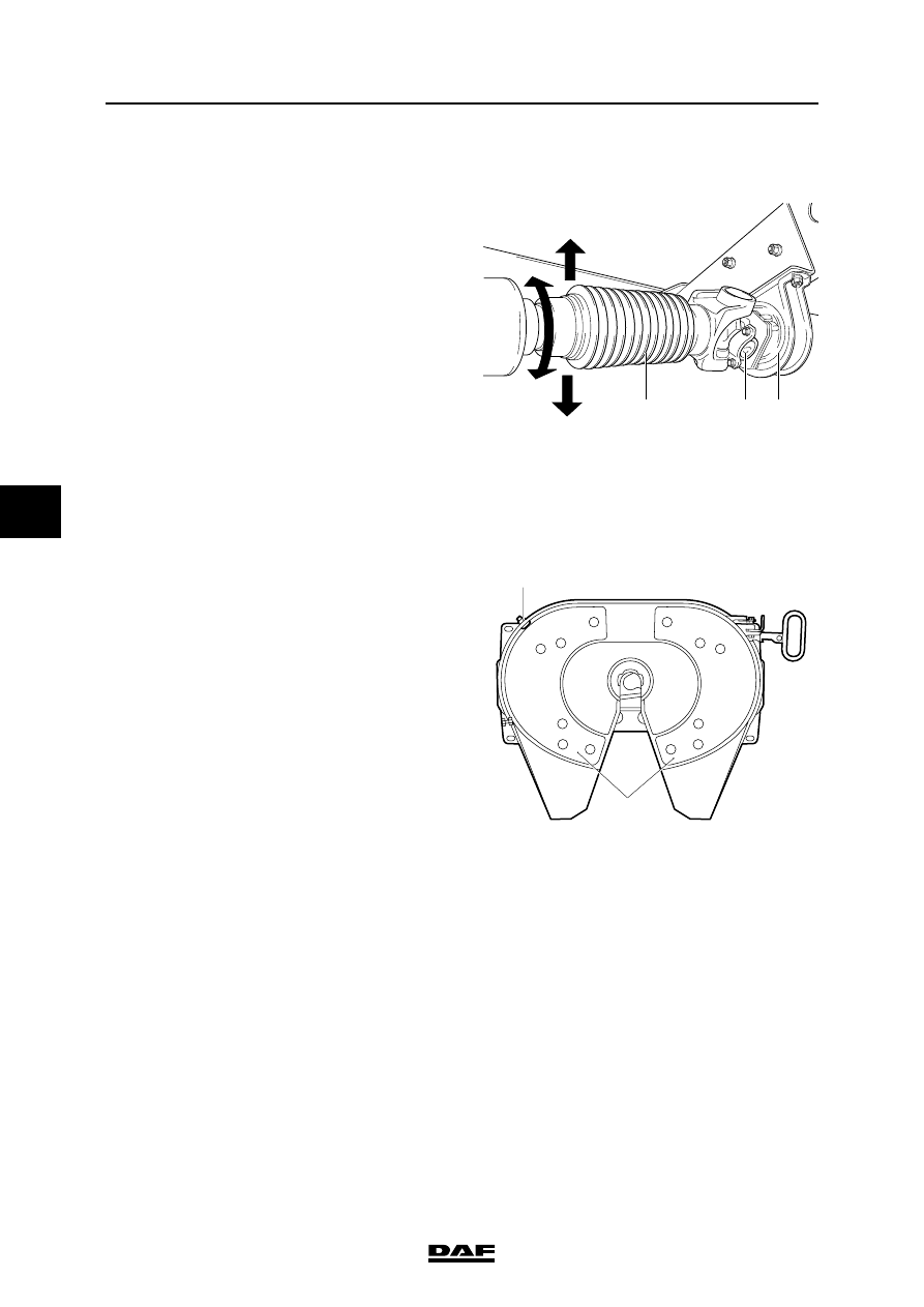
3.29 CHECK THE DRIVE SHAFT PLAY
1.
Check the universal joints (2) and
suspension bearing (3) for play and damage.
2.
Check the sliding joint for axial and radial
play. The rubber dust cover (1) over the
sliding joint should be undamaged.
3.
There must be no clearly perceptible play on
the universal joints, suspension bearing and
the sliding joint.
3.30 INSPECTING THE FIFTH WHEEL
1.
Check the attachment of the fifth wheel.
2.
Check the play of the closing gear of the fifth
wheel.
Note:
For maximum play values, consult the
manufacturer's instructions or the legal
requirements.
3.
In the case of fifth wheels with a plastic
sliding plate (1), check for wear. The plastic
sliding plate (1) must not lie flush with the top
of the attachment bolts.
1
2
3
V3 00 379
V300372
1
2
Нет комментариевНе стесняйтесь поделиться с нами вашим ценным мнением.
Текст