DAF LF45, LF55 Series. Manual — part 458
©
200436
2-11
Inspection and adjustment
BRAKE SYSTEM AND COMPONENTS
ΛΦ45/55 series
6
4
2.8 INSPECTION AND ADJUSTMENT, ADVANCE IN TRAILER VEHICLE
CONTROL VALVE
Inspection, brake pressure advance in drawn
vehicle control valve, vehicles with empty/
load relay valve
1.
Connect a pressure gauge (1) to the test
connection for the load-sensing valve and a
pressure gauge (2) to the service coupling
head.
2.
Simulate full load on the vehicle.
3.
Depress the brake pedal until the input
pressure (measured at pressure gauge 1)
is 3 bar. See "Technical data" for the
pressure that should be indicated by
pressure gauge 2.
4.
If the braking performance of the trailer
vehicle (provided it is in good condition) is
poorer than that of the prime mover, the
advance may be increased by several tenths
of a bar.
Inspection, brake pressure advance in drawn
vehicle control valve, vehicles without empty/
load relay valve
1.
Connect a pressure gauge (1) to the
measuring point on the front axle brake
cylinder and a pressure gauge (2) to the
service coupling head.
2.
Depress the brake pedal until the input
pressure (measured at pressure gauge 1)
is 3 bar. See "Technical data" for the
pressure that should be indicated by
pressure gauge 2.
3.
If the braking performance of the trailer
vehicle (provided it is in good condition) is
poorer than that of the prime mover, the
advance may be increased by several tenths
of a bar.
BRAKE SYSTEM AND COMPONENTS
2-12
©
200436
Inspection and adjustment
4
ΛΦ45/55 series
6
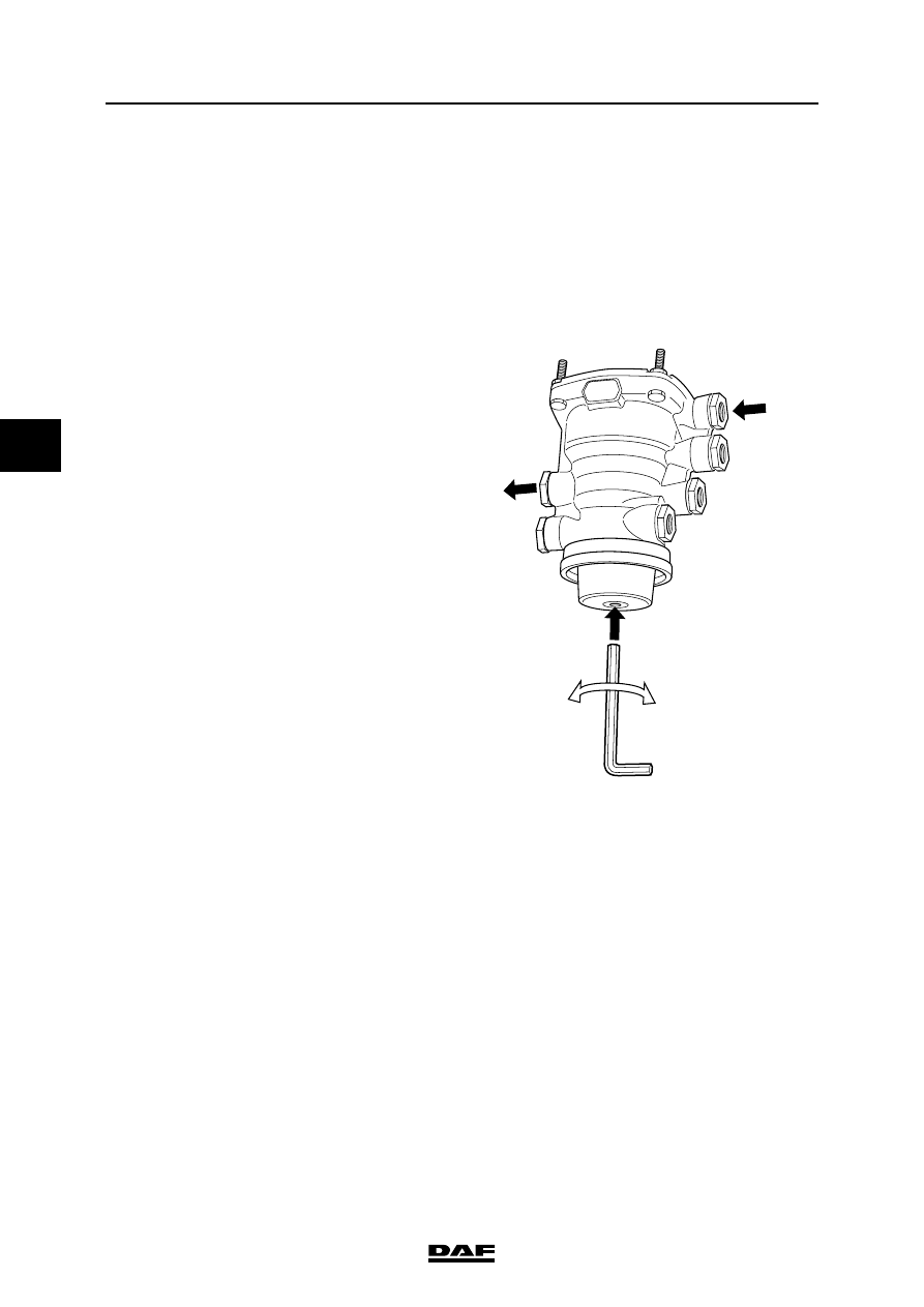
Adjusting advance in trailer vehicle control
valve
Note:
The pressure at which the readings are taken
must always be built up. If the specified pressure
is exceeded, bleed off sufficient air and once
again allow the pressure to build up.
1.
Remove the plug.
Note:
Make sure that the valve is not operated
when the advance is adjusted.
2.
Using a 6mm Allen key, turn the central
section (7) anti-clockwise or clockwise to
decrease or increase the advance
respectively.
3.
Measure the advance again.
4.
Repeat these actions until the required
advance is reached.
5.
Re-fit the plug.
41
42
3 bar
6 mm
43
11
12
+
_
22
R600341
©
200436
2-13
Inspection and adjustment
BRAKE SYSTEM AND COMPONENTS
ΛΦ45/55 series
6
4
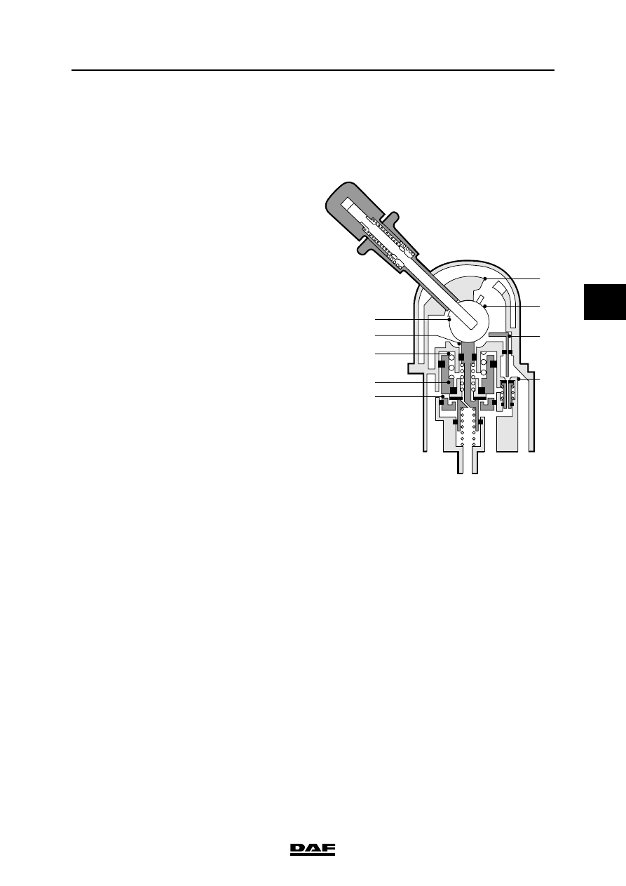
2.9 INSPECTION, PARKING BRAKE VALVE
Parking brake valve with trailer control
1.
Ensure there is sufficient system pressure.
2.
Using T-pieces, connect two pressure
gauges to connecting point 43 of the drawn
vehicle control valve and to connecting point
42 of the relay valve.
Inspecting the driving position
1.
Place the parking brake valve in the driving
position. Both pressure gauges must now
indicate a pressure of approx. 8 bar. This is
the limiting pressure of the air supply unit.
Inspecting the emergency brake
1.
Move the parking brake valve slowly towards
the parking position. Both pressure gauges
should now gradually fall to 0 bar (with the
exception of the first 10
angular
displacement. See graph in "Technical
data").
Inspecting the parking position
1.
In the parking position, both pressure
gauges should read 0 bar.
Inspecting the test position
1.
Place the parking brake valve in the parking
position, depress the handle, and move it to
the test position. The pressure gauge on
connection point 43 of the drawn vehicle
control valve valve should read approx. 8
bar. The pressure gauge at connecting point
42 of the relay valve should read 0 bar.
2.
Ensure there is sufficient system pressure.
3
21
1
22
a
2
3
5
4
6
8
7
9
10
R600092
BRAKE SYSTEM AND COMPONENTS
2-14
©
200436
Inspection and adjustment
4
ΛΦ45/55 series
6
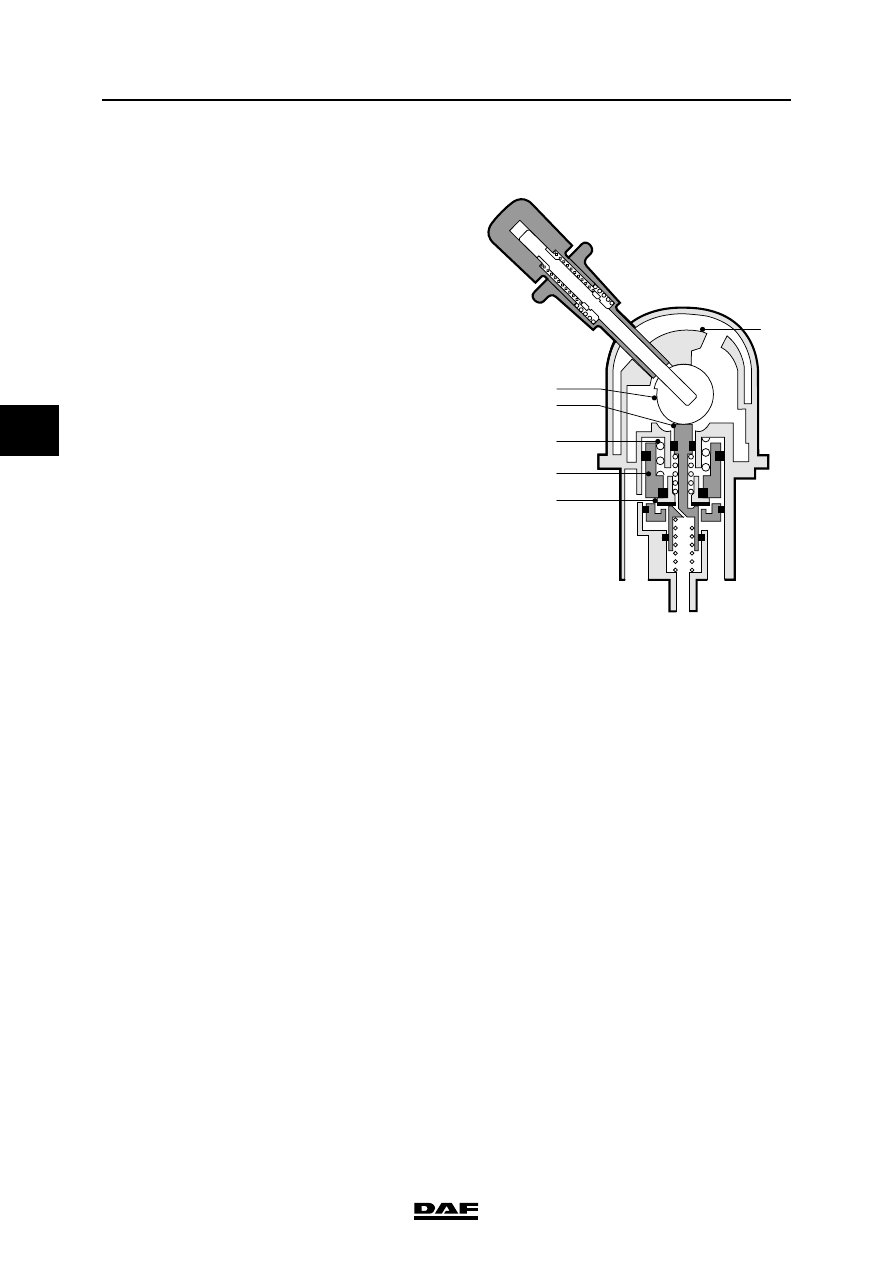
Parking-brake valve with pressure limitation
and without trailer control
1.
Connect a pressure gauge to point 42 of the
relay valve, using a tee.
Inspecting the driving position
1.
Place the parking brake valve in the driving
position. The pressure gauge must now
indicate a pressure of approx. 8 bar. This is
the limiting pressure of the air supply unit.
Inspecting the emergency brake
1.
Move the parking brake valve slowly towards
the parking position. The pressure gauge
should now gradually fall to 0 bar (with the
exception of the first 10
angular rotation -
see graph).
Inspecting the parking position
1.
In the parking position, the pressure gauge
should read 0 bar.
R600095
2
7
3
4
5
6
1
3
2
a
Нет комментариевНе стесняйтесь поделиться с нами вашим ценным мнением.
Текст