DAF LF45, LF55 Series. Manual — part 236
©
200508
2-5
Description of components
PNEUMATIC GEARBOX CONTROL
ΛΦ45/55 series
3
3
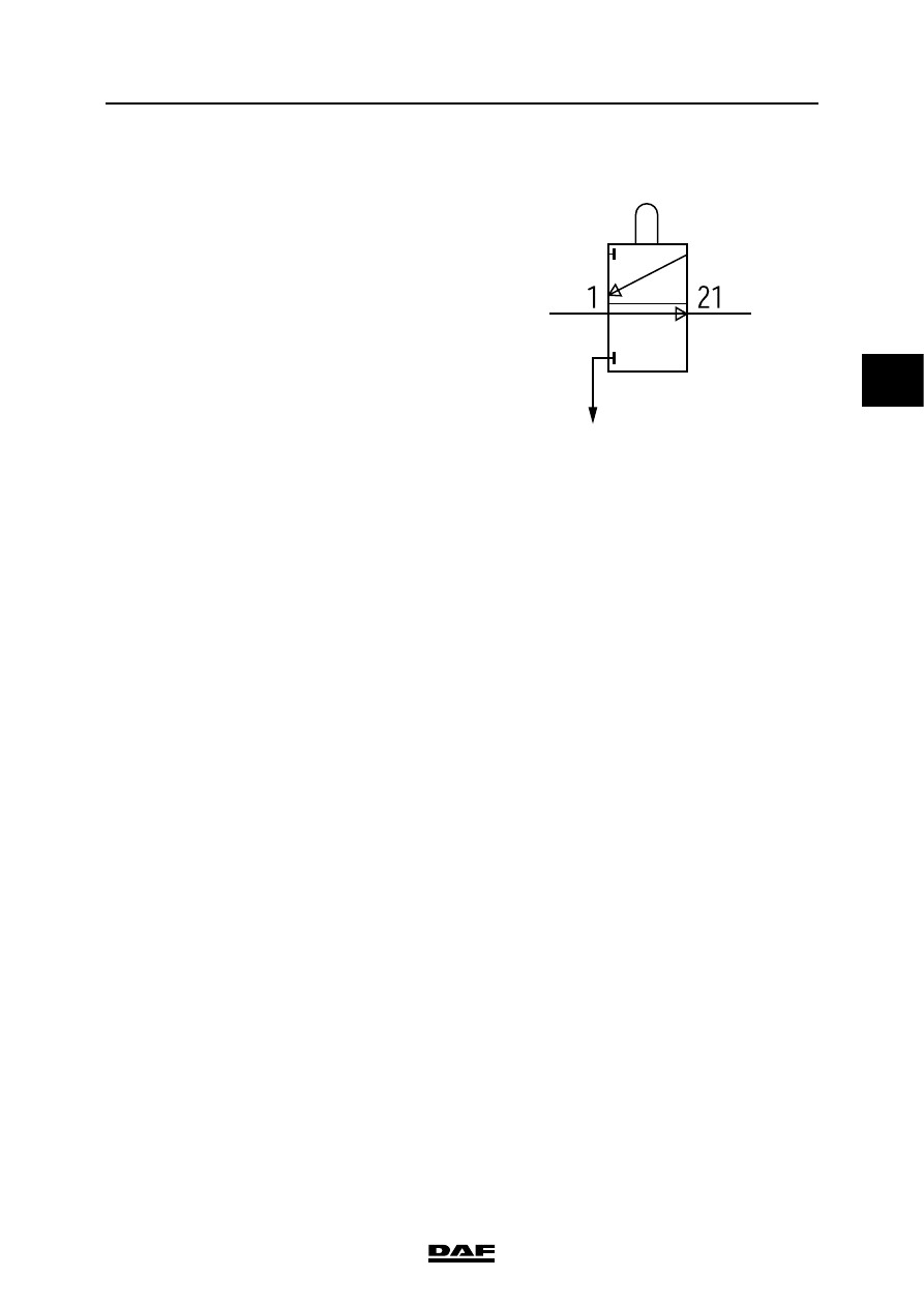
2.4 NEUTRAL POSITION VALVE
The neutral position valve is mounted on the
selector shaft housing. Inside the selector shaft is
a slot that corresponds to the neutral position of
the selector shaft. The neutral position valve pawl
drops into this slot. When a gear is engaged, the
neutral position valve pawl moves out of the slot,
thereby switching the valve. In the neutral
position the system pressure is sent to the
electropneumatic downshift protection valve. In
the event of a gear change, the gear lever and the
neutral position valve will be moved through the
neutral position. At that moment the neutral
position valve sends the system pressure from
connection (21) to the electropneumatic
downshift protection valve.
V3 00 476
PNEUMATIC GEARBOX CONTROL
2-6
©
200508
Description of components
3
ΛΦ45/55 series
3
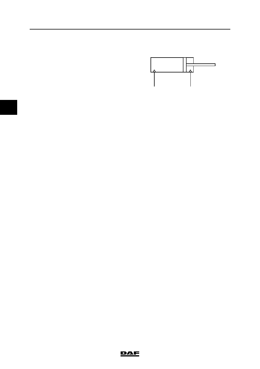
2.5 RANGE GROUP ENGAGING CYLINDER
The range group engaging cylinder is mounted
on the rear of the gearbox.
The engaging cylinder is supplied from the
electropneumatic downshift protection valve.
V3 00 479
L
H
©
200508
3-1
Inspection and adjustment
PNEUMATIC GEARBOX CONTROL
ΛΦ45/55 series
3
3
3. INSPECTION AND ADJUSTMENT
3.1 PROGRAMMING PARAMETERS USING DAVIE
After a gearbox has been replaced by a gearbox
that uses a different reduction rate, it will be
necessary to reprogram the VIC by means of
DAVIE XD.
This is to ensure that the downshift protection
valve is enabled and disabled at the correct
vehicle speeds.
It is not possible to adjust the frequencies of the
gate protection and the range-change protection
with the standard program of DAVIE XD. If the
vehicle configuration is changed, this should
always be reported.
PNEUMATIC GEARBOX CONTROL
3-2
©
200508
Inspection and adjustment
3
ΛΦ45/55 series
3
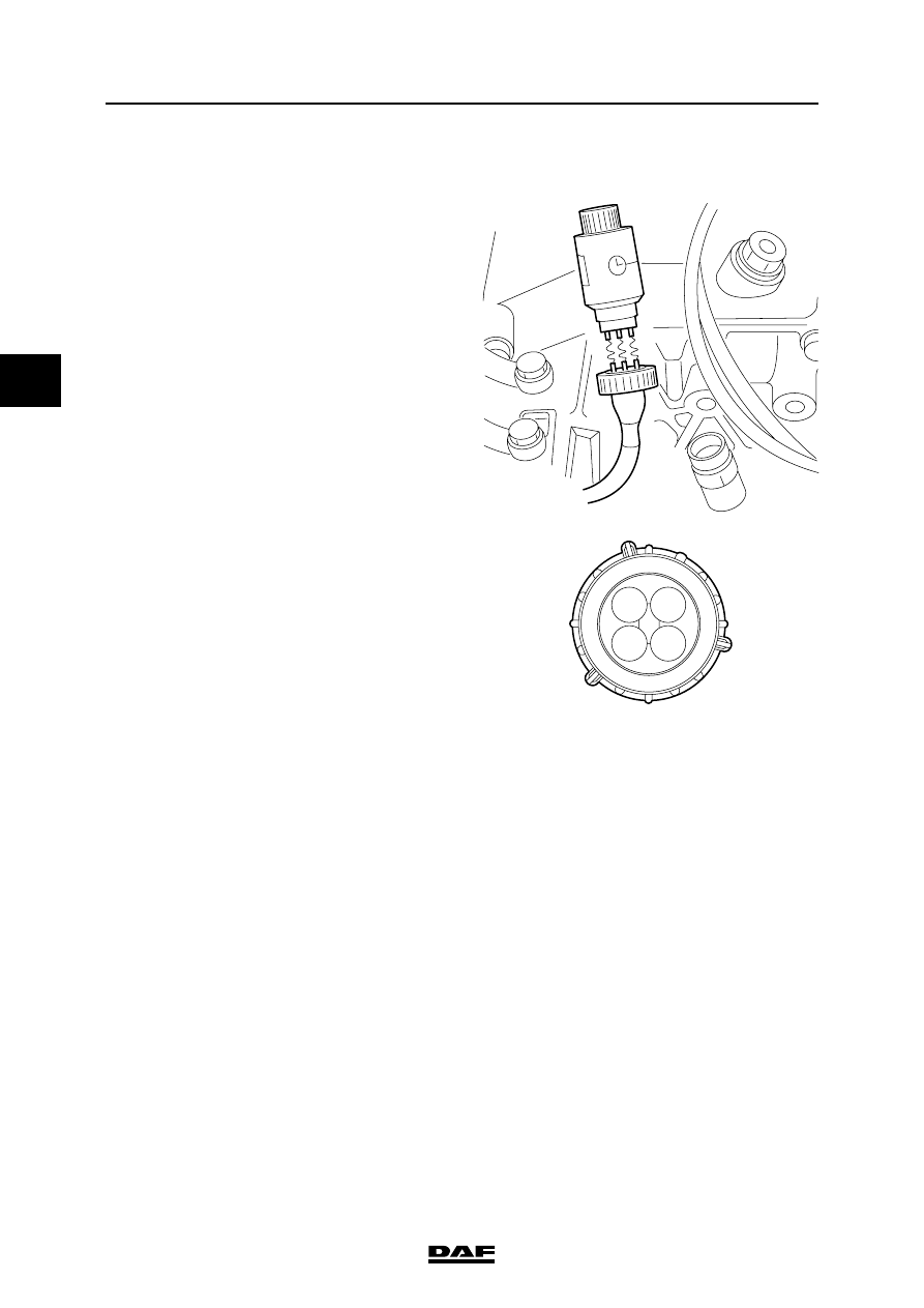
3.2 SIMULATING SPEED SIGNAL
The speed signal can be simulated with DELSI
(DAF no. 0694941). DELSI must be connected to
the speed sensor connector.
Before connecting DELSI to the speed sensor
connector, an adapter cable must be made.
The adapter cable must consist of the following
wiring:
When the speed sensor connector is
disconnected, a fault is stored in the tachograph.
This fault can be deleted using DAVIE XD.
V300425
2
4
3
1
K100873
Pin 1: speed sensor, power supply
Pin 2: speed sensor, earth
Pin 3: speed sensor, "real-time"
speed/distance signal
Pin 4: not in use
Нет комментариевНе стесняйтесь поделиться с нами вашим ценным мнением.
Текст