Dodge Dakota (ND). Manual — part 994
DISASSEMBLY
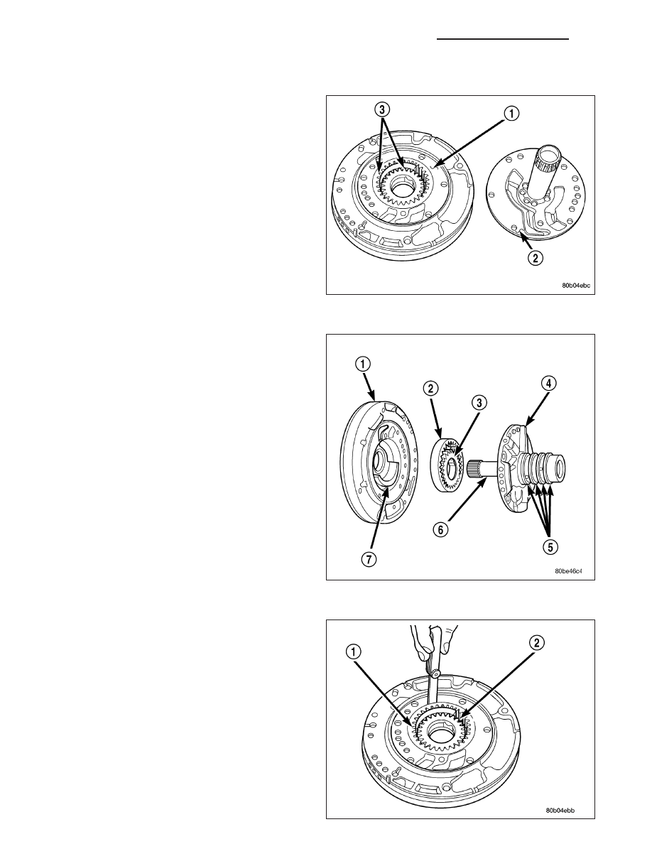
1. Remove the reaction shaft support bolts.
2. Remove the reaction shaft support(2) from the
pump housing (1).
3. Remove the pump gears (2, 3) and check for wear
and damage on pump housing (1) and gears (2, 3).
4. Re-install the gears and check clearances.
5. Measure the clearance between the outer gear (1)
and the pump pocket (2). Clearance should be
0.089-0.202 mm (0.0035-0.0079 in.).
6. Measure clearance between outer gear and cres-
cent.
Clearance
should
be
0.060-0.298
mm
(0.0023-0.0117 in.).
7. Measure clearance between inner gear and cres-
cent.
Clearance
should
be
0.093-0.385
mm
(0.0036-0.0151 in.).
8. Position an appropriate piece of Plastigage across
both pump gears.
9. Align the Plastigage to a flat area on the reaction
shaft support housing.
21 - 368
AUTOMATIC TRANSMISSION 42RLE - SERVICE INFORMATION
ND
10. Install the reaction shaft to the pump housing. Tighten the bolts to 27 N·m (20 ft. lbs.).
11. Remove bolts and carefully separate the housings. Measure the Plastigage following the instructions supplied.
12. Clearance between outer gear side and the reaction shaft support should be 0.020-0.046 mm (0.0008-0.0018
in.). Clearance between inner gear side and the reaction shaft support should be 0.020-0.046 mm (0.0008-
0.0018 in.).
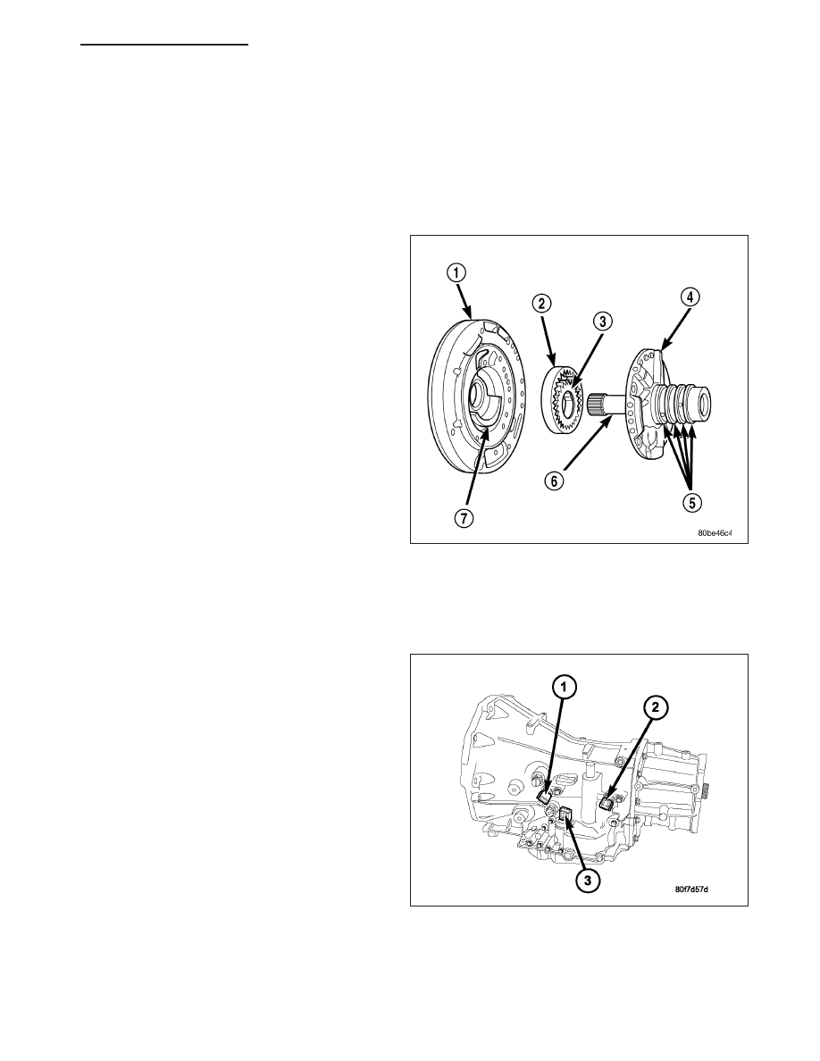
ASSEMBLY
1. Assemble oil pump as shown
2. Install and torque reaction shaft support-to-oil pump
housing bolts to 28 N·m (20 ft. lbs.) torque.
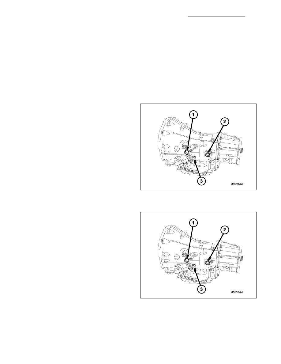
SENSOR-OUTPUT SPEED
DESCRIPTION
The Input (1) and Output (2) Speed Sensors are two-
wire magnetic pickup devices that generate AC signals
as rotation occurs. They are mounted in the left side
of the transmission case and are considered primary
inputs to the Transmission Control Module (TCM).
OPERATION
The Input Speed Sensor provides information on how fast the input shaft is rotating. As the teeth of the input clutch
hub pass by the sensor coil, an AC voltage is generated and sent to the TCM. The TCM interprets this information
as input shaft rpm.
ND
AUTOMATIC TRANSMISSION 42RLE - SERVICE INFORMATION
21 - 369
The Output Speed Sensor generates an AC signal in a similar fashion, though its coil is excited by rotation of the
rear planetary carrier lugs. The TCM interprets this information as output shaft rpm.
The TCM compares the input and output speed signals to determine the following:
•
Transmission gear ratio
•
Speed ratio error detection
•
CVI calculation
The TCM also compares the input speed signal and the engine speed signal to determine the following:
•
Torque converter clutch slippage
•
Torque converter element speed ratio
REMOVAL
1. Raise vehicle.
2. Place a suitable fluid catch pan under the transmis-
sion.
3. Remove the wiring connector from the output
speed sensor (2).
NOTE: The speed sensor bolt has a sealing patch
applied from the factory. Be sure to reuse the
same bolt.
4. Remove the bolt holding the output speed sensor
to the transmission case.
5. Remove the output speed sensor (2) from the
transmission case.
INSTALLATION
1. Install the output speed sensor (2) into the trans-
mission case.
NOTE: Before installing the speed sensor bolt, it
will be necessary to replentish the sealing patch
on the bolt using Mopar
T
Lock & Seal Adhesive.
2. Install the bolt to hold the output speed sensor into
the transmission case. Tighten the bolt to 9 N·m
(80 in.lbs.).
3. Install the wiring connector onto the output speed
sensor
4. Verify the transmission fluid level. Add fluid as nec-
essary.
5. Lower vehicle.
21 - 370
AUTOMATIC TRANSMISSION 42RLE - SERVICE INFORMATION
ND
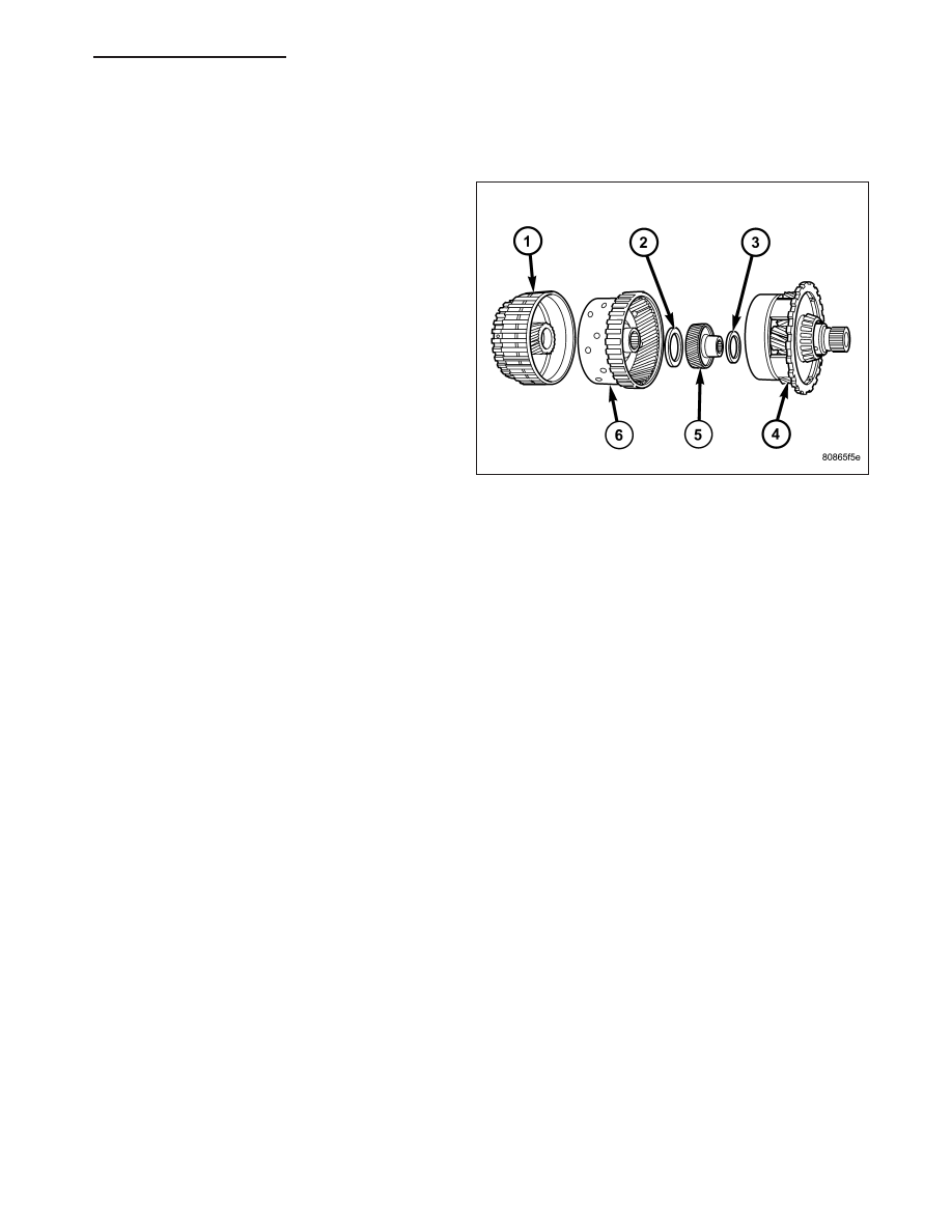
GEARTRAIN-PLANETARY
DESCRIPTION
The planetary geartrain is located between the input
clutch assembly and the rear of the transmission case.
The planetary geartrain consists of two sun gears, two
planetary carriers, two annulus (ring) gears, and one
output shaft.
OPERATION
The planetary geartrain utilizes two planetary gear sets that connect the transmission input shaft to the output shaft.
Input and holding clutches drive or lock different planetary members to change output ratio or direction.
SEAL-OIL PUMP
REMOVAL
1. Remove the transmission from the vehicle (Refer to 21 - TRANSMISSION/AUTOMATIC - 42RLE - REMOVAL).
2. Remove the torque converter from the transmission bellhousing.
3. Use special tool C-3981B to remove oil pump seal.
INSTALLATION
1. Clean and inspect oil pump seal seat. Then install seal using special tool C-4193-A.
2. Clean and inspect torque converter hub. If nicks, scratches or hub wear are found, torque converter replacement
will be required.
CAUTION: If the torque converter is being replaced, apply a light coating of grease to the crankshaft pilot
hole. Also inspect the engine drive plate for cracks. If any cracks are found replace the drive plate. Do not
attempt to repair a cracked drive plate. Always use new torque converter to drive plate bolts.
3. Apply a light film of transmission oil to the torque converter hub and oil seal lips. Then install torque converter
into transmission. Be sure that the hub lugs mesh with the front pump lugs when installing.
4. Reinstall the transmission into the vehicle. (Refer to 21 - TRANSMISSION/TRANSAXLE/AUTOMATIC - 42RLE -
INSTALLATION)
MECHANISM-SHIFT
DESCRIPTION
The gear shift mechanism provides six shift positions which are:
•
Park (P)
•
Reverse (R)
•
Neutral (N)
ND
AUTOMATIC TRANSMISSION 42RLE - SERVICE INFORMATION
21 - 371
Нет комментариевНе стесняйтесь поделиться с нами вашим ценным мнением.
Текст