Dodge Dakota (ND). Manual — part 993
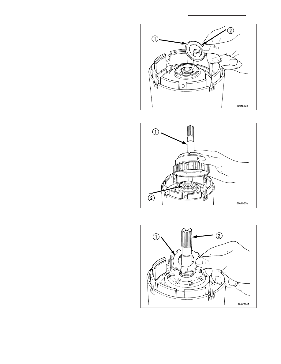
40. Install the number 2 needle bearing (1).
41. Install the underdrive shaft assembly (1).
42. Install the number 3 thrust washer (1) to the
underdrive shaft assembly (2). Be sure five tabs
are seated properly.
21 - 364
AUTOMATIC TRANSMISSION 42RLE - SERVICE INFORMATION
ND
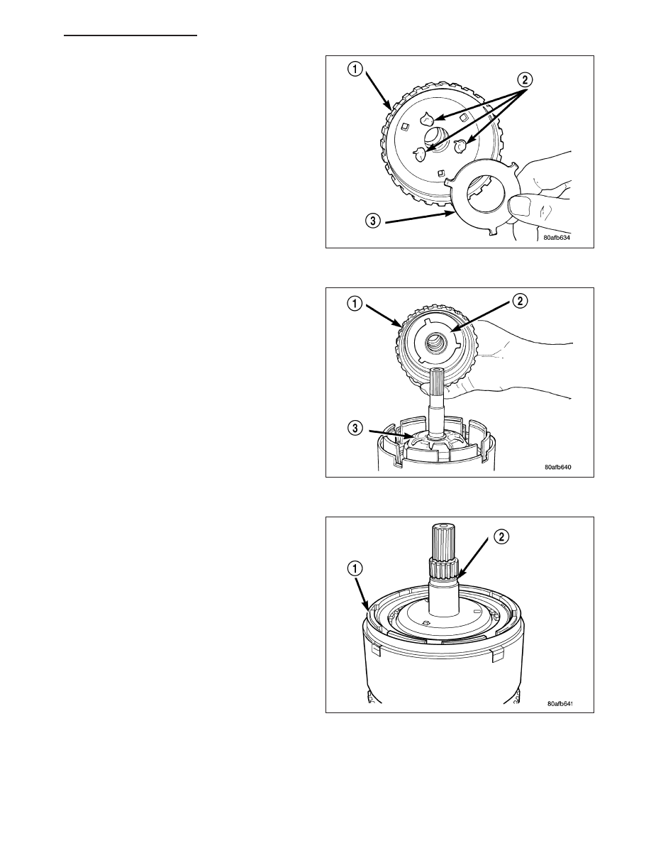
43. Install the number 3 thrust plate (3) to the bottom
of the overdrive shaft assembly (1). Retain with
petrolatum or transmission assembly gel (2).
44. Install the overdrive shaft assembly (1).
45. Reinstall overdrive and reverse clutch. Recheck-
ing these clutch clearances is not necessary.
ND
AUTOMATIC TRANSMISSION 42RLE - SERVICE INFORMATION
21 - 365
SENSOR-INPUT SPEED
DESCRIPTION
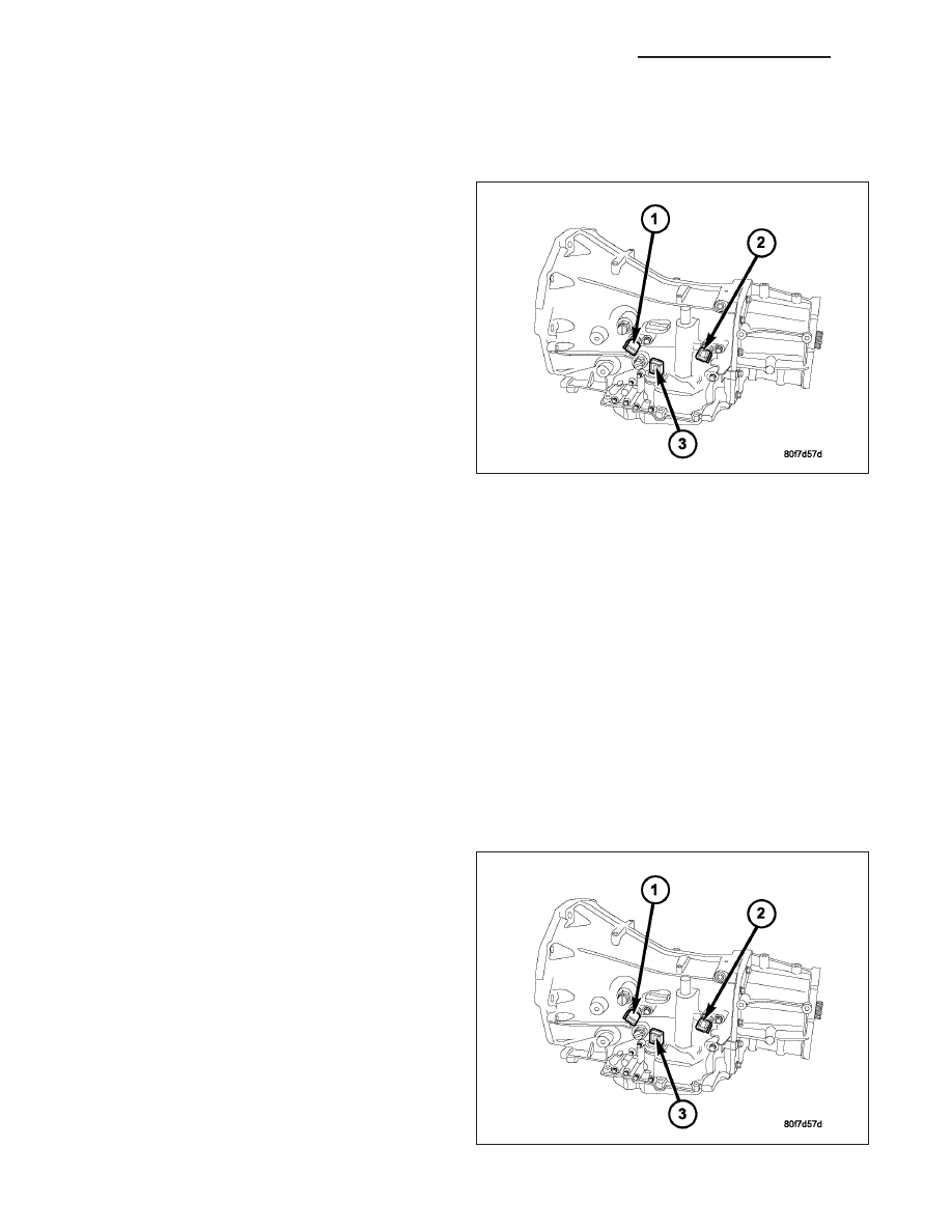
The Input (1) and Output (2) Speed Sensors are two-
wire magnetic pickup devices that generate AC signals
as rotation occurs. They are mounted in the left side
of the transmission case and are considered primary
inputs to the Transmission Control Module (TCM).
OPERATION
The Input Speed Sensor provides information on how fast the input shaft is rotating. As the teeth of the input clutch
hub pass by the sensor coil, an AC voltage is generated and sent to the TCM. The TCM interprets this information
as input shaft rpm.
The Output Speed Sensor generates an AC signal in a similar fashion, though its coil is excited by rotation of the
rear planetary carrier lugs. The TCM interprets this information as output shaft rpm.
The TCM compares the input and output speed signals to determine the following:
•
Transmission gear ratio
•
Speed ratio error detection
•
CVI calculation
The TCM also compares the input speed signal and the engine speed signal to determine the following:
•
Torque converter clutch slippage
•
Torque converter element speed ratio
REMOVAL
1. Raise vehicle.
2. Place a suitable fluid catch pan under the transmis-
sion.
3. Remove the wiring connector from the input speed
sensor.
NOTE: The speed sensor bolt has a sealing patch
applied from the factory. Be sure to reuse the
same bolt.
4. Remove the bolt holding the input speed sensor to
the transmission case.
5. Remove the input speed sensor from the transmis-
sion case.
21 - 366
AUTOMATIC TRANSMISSION 42RLE - SERVICE INFORMATION
ND
INSTALLATION
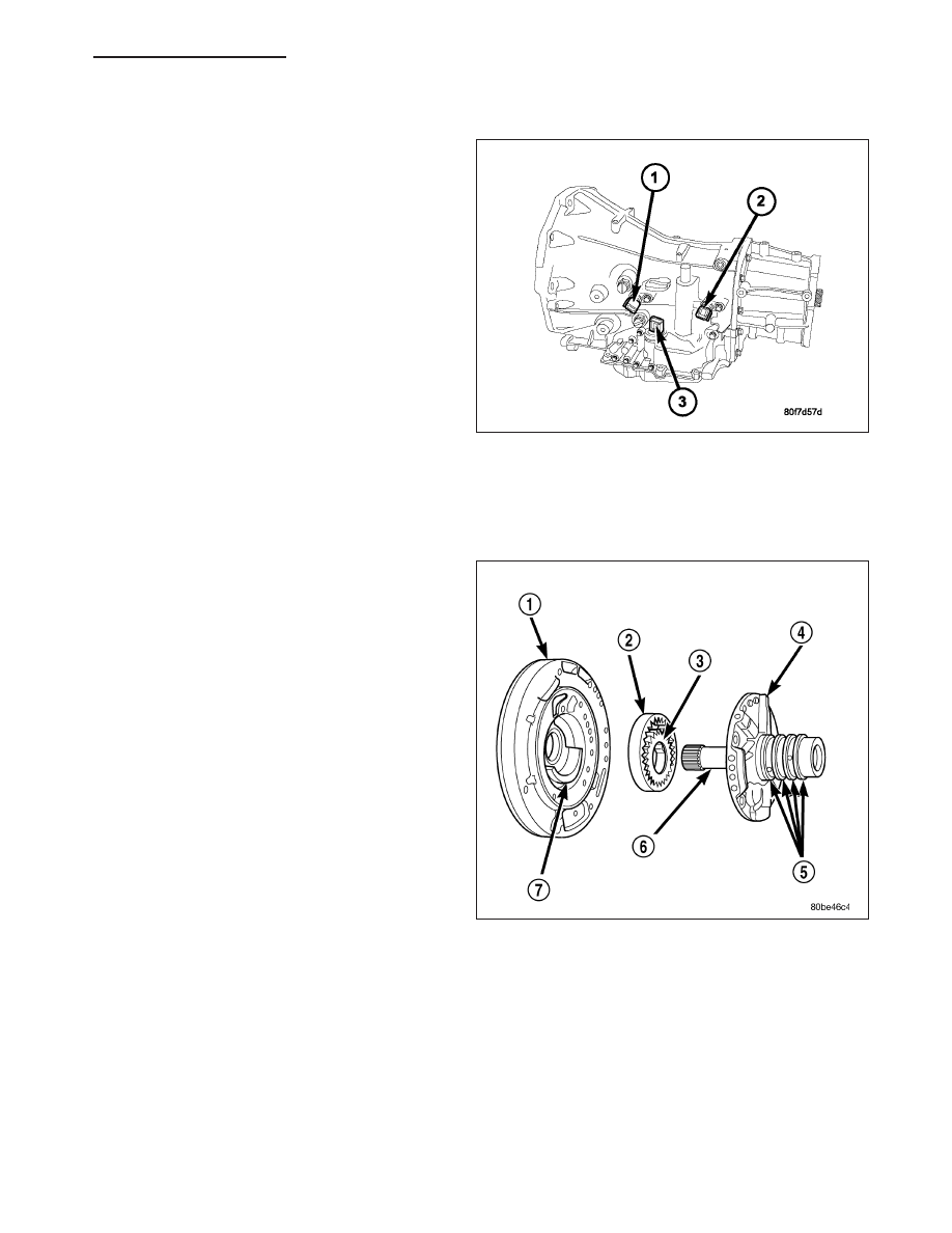
1. Install the input speed sensor (1) into the transmis-
sion case.
NOTE: Before installing the speed sensor bolt, it
will be necessary to replentish the sealing patch
on the bolt using Mopar
T
Lock & Seal Adhesive.
2. Install the bolt to hold the input speed sensor into
the transmission case. Tighten the bolt to 9 N·m
(80 in.lbs.).
3. Install the wiring connector onto the input speed
sensor
4. Verify the transmission fluid level. Add fluid as nec-
essary.
5. Lower vehicle.
PUMP-OIL
DESCRIPTION
The oil pump is located in the pump housing inside
the bell housing of the transmission case. The oil
pump assembly consists of an inner (3) and outer (2)
gear, a housing (1), and a cover that also serves as
the reaction shaft support (6).
OPERATION
As the torque converter rotates, the converter hub rotates the inner and outer gears. As the gears rotate, the clear-
ance between the gear teeth increases in the crescent area, and creates a suction at the inlet side of the pump.
This suction draws fluid through the pump inlet from the oil pan. As the clearance between the gear teeth in the
crescent area decreases, it forces pressurized fluid into the pump outlet and to the valve body.
ND
AUTOMATIC TRANSMISSION 42RLE - SERVICE INFORMATION
21 - 367
Нет комментариевНе стесняйтесь поделиться с нами вашим ценным мнением.
Текст