Dodge Dakota (ND). Manual — part 899
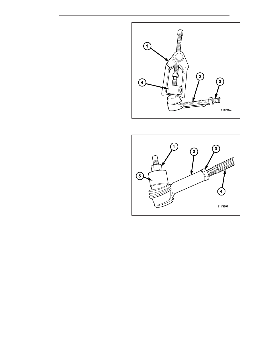
3. Separate the outer tie rod end (2) from the knuckle
with Remover C3894–A (1).
4. Unthread the outer tie rod end (2) from the inner tie
rod (3). Count the number of turns when remov-
ing the tie rod end, This will give a good start-
ing
point
when
reassembiling
and
toe
adjustment.
INSTALLATION - OUTER TIE ROD END
NOTE: Do not twist the boot at anytime during
removal or installation.
1. Thread the outer tie rod end (2) onto the inner tie
rod (4), to it’s original position.
2. Install the outer tie rod end into the steering
knuckle (5).
3. Tighten the ball stud nut (1) on the ball stud to 75
N·m (55 ft. lbs.).
4. Set wheel toe pattern, (Refer to 2 - SUSPENSION/
WHEEL
ALIGNMENT
-
STANDARD
PROCE-
DURE).
5. Tighten jam nut (3) to 75 N·m (55 ft. lbs.).
19 - 36
LINKAGE
ND
PUMP
TABLE OF CONTENTS
page
page
PUMP
. . . . . . . . . . . . . . . . . . . . . . . . . 37
. . . . . . . . . . . . . . . . . . . . . . . . . . . 37
. . . . . . . . . . . . . . . . . . . . . . 37
OPERATION . . . . . . . . . . . . . . . . . . . . . . . . . 38
. . . . . . . . . . . . . . . . . . . . . . . . . . . . . 38
. . . . . . . . . . . . . . . . . . . . . . . . . 39
. . . . . . . . . . . . . . . . . . . . . . 40
FLUID
. . . . . . . . . . . . . . . . . . . . . . . . . 40
CHECKING . . . . . . . . . . . . . . . . . . . . . . . . . . 40
FLUID COOLER
. . . . . . . . . . . . . . . . . . . . . . . . . . . . . 41
. . . . . . . . . . . . . . . . . . . . . . . . . 42
HOSES
RETRUN HOSE - COOLER TO RESERVOIR
. . . . . . . . . . . . . . . . . . . . . 44
RETURN HOSE - COOLER TO RESERVOIR
. . . . . . . . . . . . . . . . . . . . . 47
RESERVOIR
. . . . . . . . . . . . . . . . . . . . . . . . . . . . . 47
. . . . . . . . . . . . . . . . . . . . . . . . . 47
PULLEY
. . . . . . . . . . . . . . . . . . . . . . . . . . . . . 48
. . . . . . . . . . . . . . . . . . . . . . . . . 48
PUMP
DESCRIPTION
The pump is connected to the steering gear via the pressure hose and the return hoses. The pump shaft has a
pressed-on pulley that is belt driven by the crankshaft pulley.
The power steering oil cooler is mounted to the front lower part of the radiator.
NOTE: Power steering pumps are not interchangeable with pumps installed on other vehicles.
OPERATION
Hydraulic pressure is provided for the power steering gear by the belt driven power steering pump. The power steer-
ing pumps are constant flow rate and displacement, vane-type pumps.
DIAGNOSIS AND TESTING
PUMP LEAKAGE
The pump is serviced as an assembly and should not be disassembled. Plastic pump reservoirs can be replace and
the reservoir O-ring.
Check for leaks in the following areas:
•
Pump shaft seal behind the pulley
•
Pump to reservoir O-ring
•
Reservoir cap
•
Pressure and return lines
•
Flow control valve fitting
ND
PUMP
19 - 37
STANDARD PROCEDURE
POWER STEERING PUMP - INITIAL OPERATION
WARNING: THE FLUID LEVEL SHOULD BE CHECKED WITH ENGINE OFF TO PREVENT INJURY FROM MOV-
ING COMPONENTS.
CAUTION: MOPAR
T
ATF+4 is to be used in the power steering system. No other power steering or auto-
matic transmission fluid is to be used in the system. Damage may result to the power steering pump and
system if any other fluid is used, and do not overfill.
Wipe filler cap clean, then check the fluid level. The dipstick should indicate COLD when the fluid is at normal
temperature.
1. Turn steering wheel all the way to the left
2. Fill the pump fluid reservoir to the proper level and let the fluid settle for at least two (2) minutes.
3. Raise the front wheels off the ground.
4. Slowly turn the steering wheel lock-to-lock 20 times with the engine off while checking the fluid level.
NOTE: Vehicles with long return lines or oil coolers turn wheel 40 times.
5. Start the engine. With the engine idling maintain the fluid level.
6. Lower the front wheels and let the engine idle for two minutes.
7. Turn the steering wheel in both direction and verify power assist and quiet operation of the pump.
If the fluid is extremely foamy or milky looking, allow the vehicle to stand a few minutes and repeat the procedure.
CAUTION: Do not run a vehicle with foamy fluid for an extended period. This may cause pump damage.
REMOVAL
1. Drain and siphon the power steering fluid from the
pump.
2. Remove the serpentine drive belt, (Refer to 7 -
COOLING/ACCESSORY DRIVE/DRIVE BELTS -
REMOVAL).
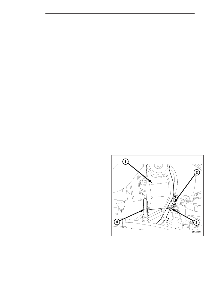
3. Remove the reservoir return hose (3) at the reser-
voir (1).
19 - 38
PUMP
ND
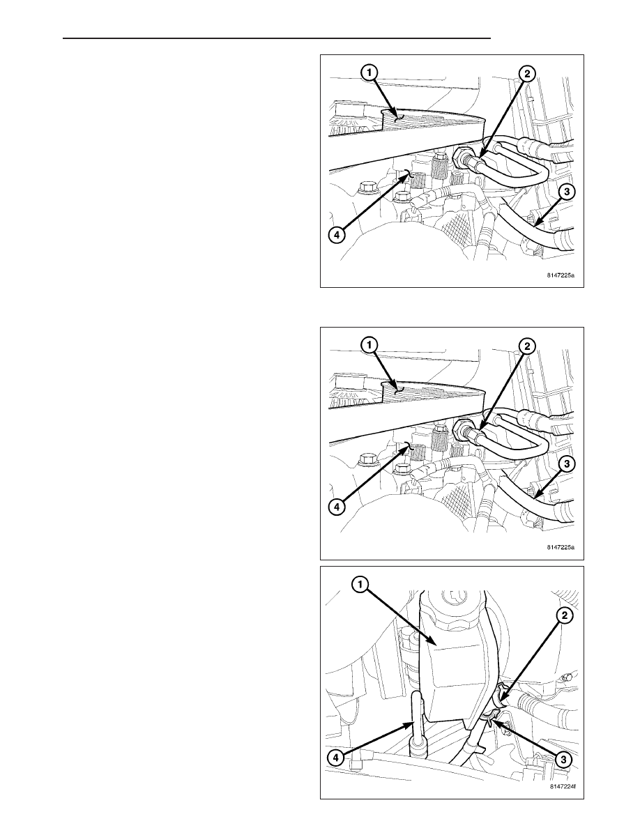
4. Remove the pressure hose (2) from the pump.
5. Remove 3 pump mounting bolts through pulley (1)
access holes.
6. Remove the pump (4) from the engine.
INSTALLATION
1. Align the pump (4) with the mounting holes on the
engine.
2. Install 3 pump mounting bolts through the pulley
access holes (1). Tighten the bolts to 28 N·m (21 ft.
lbs.).
3. Install the pressure hose (2) to the pump (4).
Tighten the pressure hose to 31 N·m (23 ft. lbs.).
4. Install reservoir return hose (3) to the reservoir (1).
5. Install the serpentine drive belt, (Refer to 7 -
COOLING/ACCESSORY DRIVE/DRIVE BELTS -
INSTALLATION).
6. Fill the power steering pump, (Refer to 19 -
STEERING/PUMP - STANDARD PROCEDURE).
ND
PUMP
19 - 39
Нет комментариевНе стесняйтесь поделиться с нами вашим ценным мнением.
Текст