Dodge Dakota (ND). Manual — part 898
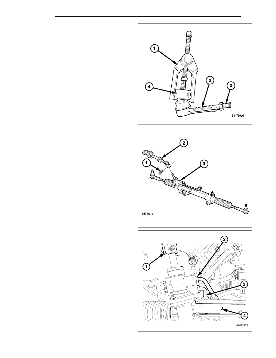
6. Separate tie rod ends (2) from the knuckles with
Puller C3894–A (1) (Refer to 19 - STEERING/
LINKAGE/TIE ROD END - REMOVAL).
7. Remove the steering gear pinch bolt (1).
8. Remove the lower steering coupling (2) from the
steering gear (3).
9. Turn the steering gear to the full right position.
NOTE: Protect the end of hoses to prevent con-
tamination to the system and damage to the
o-rings.
10. Remove the power steering lines (2&3) from the
gear (4). (Refer to 19 - STEERING/PUMP/HOSES
- REMOVAL).
19 - 32
GEAR
ND
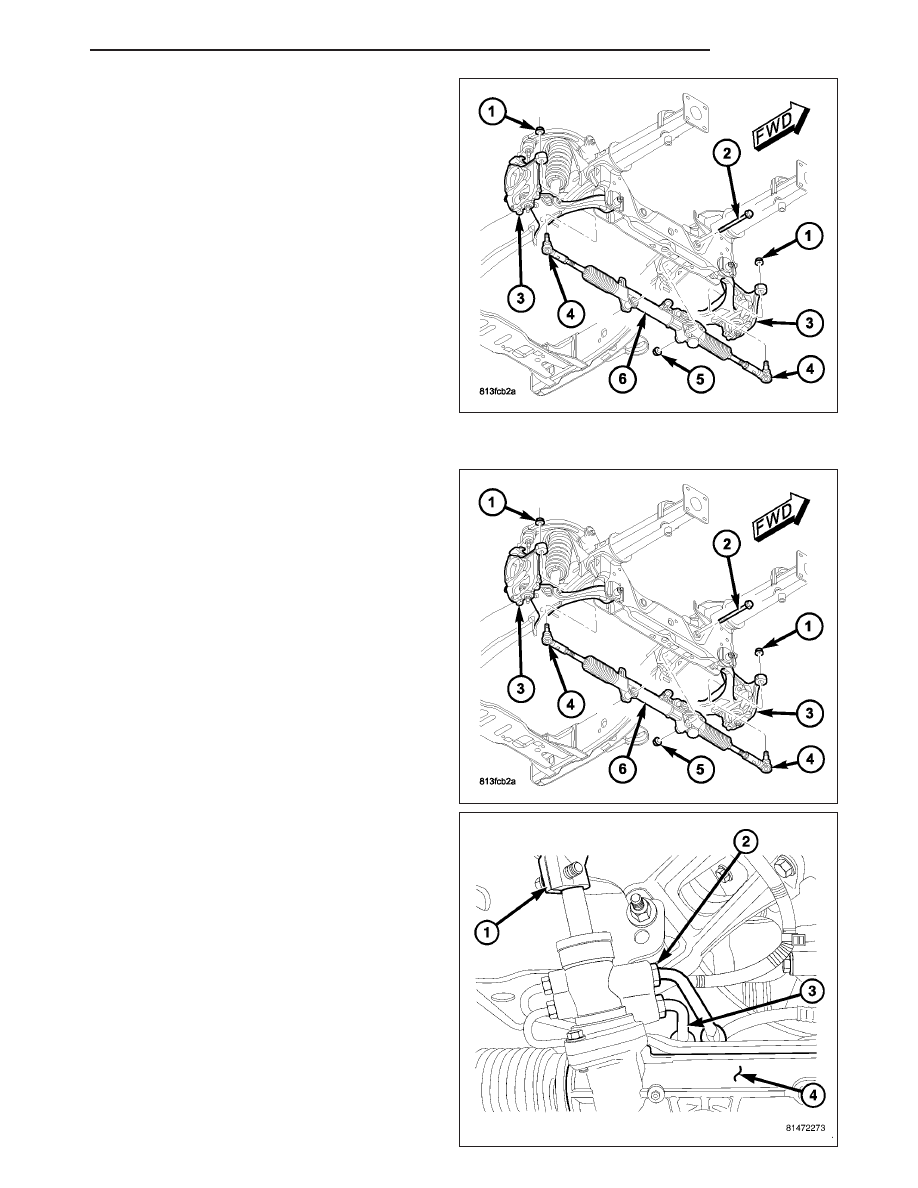
11. Remove the steering gear mounting bolts (2) and
nuts (5).
12. Tip the gear (6) forward to allow clearance and
move to the right then tip the gear downward on
the left side to remove from the vehicle.
INSTALLATION
NOTE: Before installing gear inspect bushings and
replace if worn or damaged.
1. Install gear (6) to the vehicle and tighten mounting
nuts (5) and bolts (2) to 258 N·m (190 ft. lbs.).
2. Install power steering lines (2&3) to steering gear
(4) and tighten the pressure hose to 31 N·m (23 ft.
lbs.) and tighten the return hose to 37 N·m (27 ft.
lbs.). (Refer to 19 - STEERING/PUMP/HOSES -
INSTALLATION).
3. Slide the shaft coupler (1) onto gear (4). Install
new bolt (1) and tighten to 49 N·m (36 ft. lbs.).
ND
GEAR
19 - 33
4. Clean tie rod end studs and knuckle tapers (5).
5. Install tie rod ends (2) into the steering knuckles (5)
and tighten the nuts (1) to 75 N·m (55 ft. lbs.).
(Refer to 19 - STEERING/LINKAGE/TIE ROD END
- INSTALLATION).
6. Install the front tires.
7. Remove the support and lower the vehicle.
8. Unlock the steering wheel.
9. Fill system with fluid, (Refer to 19 - STEERING/PUMP - STANDARD PROCEDURE).
10. Adjust the toe position. (Refer to 2 - SUSPENSION/WHEEL ALIGNMENT - STANDARD PROCEDURE).
SPECIFICATIONS
TORQUE CHART
TORQUE SPECIFICATIONS
DESCRIPTION
N·m
Ft. Lbs.
In. Lbs.
Rack and Pinion Steering
Gear
Gear to Frame Bolts
258
190
—
Rack and Pinion Steering
Gear
Intermediate Shaft Bolt
38
28
—
Tie Rod End
Knuckle Nut
75
55
—
Tie Rod End
Jam Nut
75
55
—
Power Steering Line
Pressure Line
31
23
—
Power Steering Line
Return Line
37
27
—
19 - 34
GEAR
ND
LINKAGE
TABLE OF CONTENTS
page
page
LINKAGE
. . . . . . . . . . . . . . . . . . 35
TIE ROD END
INSTALLATION - OUTER TIE ROD END
LINKAGE
DIAGNOSIS AND TESTING
OUTER TIE ROD END
NOTE: If the outer tie rod end is equipped with a lubrication fitting, grease the joint then road test the vehi-
cle before performing test.
1. Raise the front of the vehicle. Place safety floor stands under both lower control arms as far outboard as pos-
sible. Lower the vehicle to allow the stands to support some or all of the vehicle weight.
2. Remove the front tires.
3. Mount a dial indicator solidly to the vehicle steering knuckle and then zero the dial indicator.
4. Position indicator plunger on the topside of the outer tie rod end.
NOTE: The dial indicator plunger must be perpendicular to the machined surface of the outer tie rod end.
5. Position a pry bar in order to pry downwards on the outer tie rod end.
6. If the travel exceeds 0.5 mm (0.020 in.), replace the outer tie rod end (Refer to 19 - STEERING/LINKAGE/TIE
ROD END - REMOVAL).
7. If the outer tie rod end is within specs reinstall the front tires (Refer to 22 - TIRES/WHEELS/WHEELS - STAN-
DARD PROCEDURE).
TIE ROD END
REMOVAL - OUTER TIE ROD END
NOTE: Do not twist the boot anytime during
removal or installation.
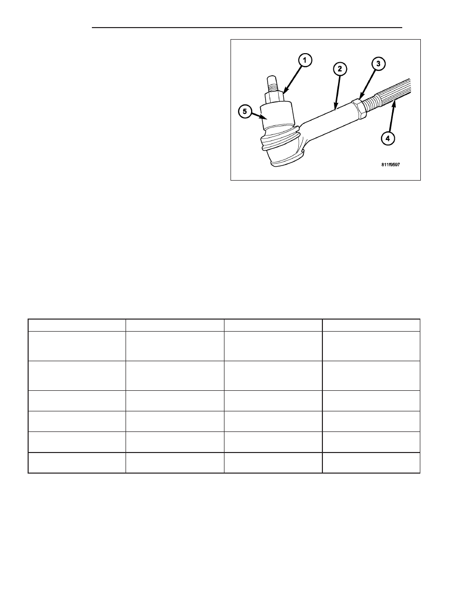
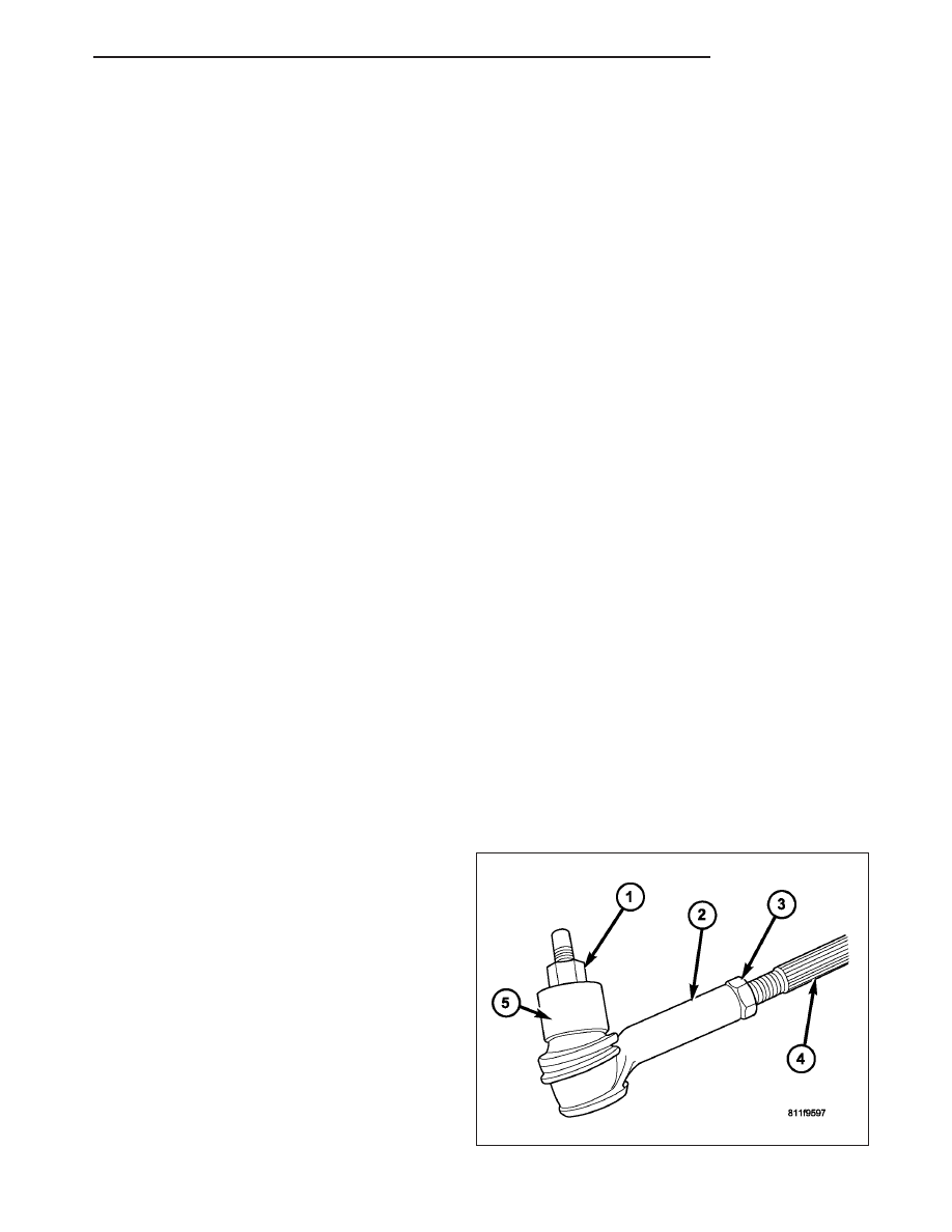
1. Loosen the jam nut (3).
2. Remove the outer tie rod end (2) nut (1) from the
ball stud.
ND
LINKAGE
19 - 35
Нет комментариевНе стесняйтесь поделиться с нами вашим ценным мнением.
Текст