Dodge Dakota (ND). Manual — part 112

U0002–CAN C BUS OFF PERFORMANCE (340) (CONTINUED)
For a complete wiring diagram Refer to Section 8W.
•
When Monitored:
Continuously.
•
Set Condition:
Whenever the CAN C Bus (+) or CAN C Bus (-) is open, shorted to voltage or shorted to ground.
Possible Causes
INTERMITTENT CAN C BUS OFF PERFORMANCE DTC
CAN C BUS DTCs SET IN FRONT CONTROL MODULE
(D65) CAN C BUS (+) CIRCUIT OPEN
(D64) CAN C BUS (-) CIRCUIT OPEN
ANTI-LOCK BRAKE MODULE
Diagnostic Test
1.
DTC IS ACTIVE
Ignition on, engine not running.
With the scan tool, clear DTCs in the Anti-lock Brake Module.
Cycle the ignition from off to on at least 5 times, leaving the ignition on for a minimum of 90 seconds per cycle.
With the scan tool, select View DTCs in the Anti-lock Brake Module.
Does the DTC reset and/or remain active?
Yes
>> Go to 2
No
>> Go to 6
2.
CAN C BUS DTCs SET IN FRONT CONTROL MODULE
With the scan tool, select View DTCs in the Front Control Module (FCM).
Are there any active CAN C Bus DTCs?
Yes
>> Refer to 8 — ELECTRICAL/ELECTRONIC CONTROL MODULES — DIAGNOSIS AND TESTING for
diagnostic procedures and for further possible causes.
No
>> Go to 3
5 - 218
BRAKES - ABS ELECTRICAL DIAGNOSTICS
ND
U0002–CAN C BUS OFF PERFORMANCE (340) (CONTINUED)
3.
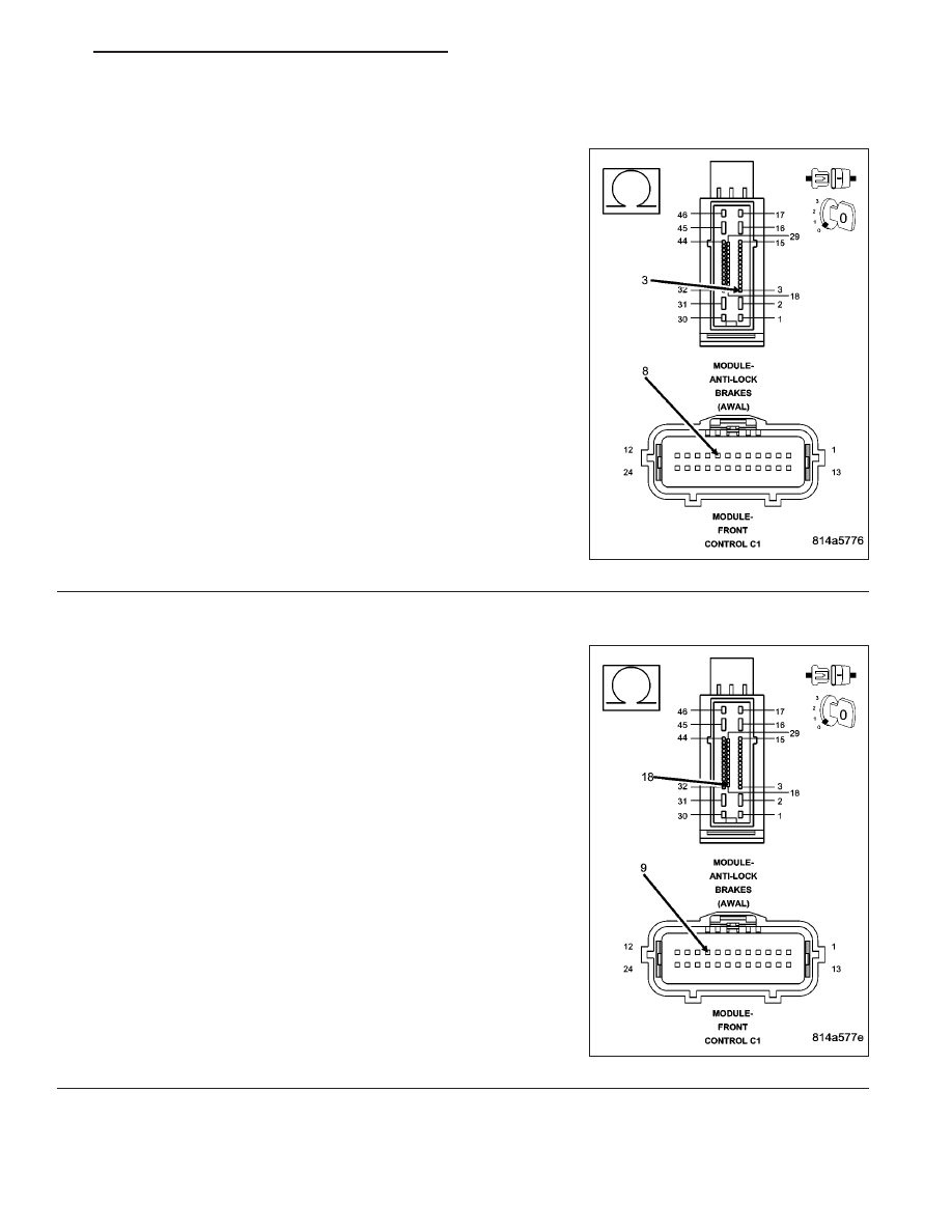
(D65) CAN C BUS (+) CIRCUIT OPEN
Turn the ignition off.
Disconnect the Anti-lock Brake Module harness connector.
Disconnect the Front Control Module C1 harness connector.
Measure the resistance of the (D65) CAN C Bus (+) circuit between
the Anti-lock Brake Module harness connector and the Front Control
Module C1 harness connector.
Is the resistance above 2.0 ohms?
Yes
>> Repair the (D65) CAN C Bus (+) circuit for an open.
Perform ABS VERIFICATION TEST - VER 1. (Refer to 5 -
BRAKES/ELECTRICAL - DIAGNOSIS AND TESTING)
No
>> Go to 4
4.
(D64) CAN C BUS (-) CIRCUIT OPEN
Measure the resistance of the (D64) CAN C Bus (-) circuit between
the Anti-lock Brake Module harness connector and the Front Control
Module C1 harness connector.
Is the resistance above 2.0 ohms?
Yes
>> Repair the (D64) CAN C Bus (-) circuit for an open.
Perform ABS VERIFICATION TEST - VER 1. (Refer to 5 -
BRAKES/ELECTRICAL - DIAGNOSIS AND TESTING)
No
>> Go to 5
ND
BRAKES - ABS ELECTRICAL DIAGNOSTICS
5 - 219
U0002–CAN C BUS OFF PERFORMANCE (340) (CONTINUED)
5.
ANTI-LOCK BRAKE MODULE
Inspect the wiring between the Anti-lock Brake Module harness connector and the Front Control Module harness
connector. If any problems are found, repair as necessary. If no problems are found, view repair.
Repair
Replace the Anti-lock Brake Module in accordance with the Service Information.
Perform ABS VERIFICATION TEST - VER 1. (Refer to 5 - BRAKES/ELECTRICAL - DIAGNOSIS AND
TESTING)
6.
INTERMITTENT CAN C BUS OFF PERFORMANCE DTC
The conditions necessary to set this DTC are not present at this time.
Using the wiring diagram/schematic as a guide, inspect the wiring and connectors.
While monitoring the scan tool data relative to this circuit, wiggle test the wiring and connectors.
Look for the data to change or for the DTC to reset during the wiggle test.
Were any problems found?
Yes
>> Repair as necessary.
Perform ABS VERIFICATION TEST - VER 1. (Refer to 5 - BRAKES/ELECTRICAL - DIAGNOSIS AND
TESTING)
No
>> Test complete.
5 - 220
BRAKES - ABS ELECTRICAL DIAGNOSTICS
ND
U0100–LOST COMMUNICATION WITH FRONT CONTROL MODULE (340)
For a complete wiring diagram Refer to Section 8W.
Diagnostic Test
1.
LOST COMMUNICATION WITH POWERTRAIN CONTROL MODULE (PCM)
The Anti-lock Brake Module is reporting that network communication has been lost with the Powertrain Control Mod-
ule (PCM).
View repair.
Repair
Refer to 8 — ELECTRICAL/ELECTRONIC CONTROL MODULES — DIAGNOSIS AND TESTING for
diagnostic procedures and for further possible causes.
ND
BRAKES - ABS ELECTRICAL DIAGNOSTICS
5 - 221
Нет комментариевНе стесняйтесь поделиться с нами вашим ценным мнением.
Текст