Dodge Dakota (ND). Manual — part 113
U0141–LOST COMMUNICATION WITH FRONT CONTROL MODULE (340)
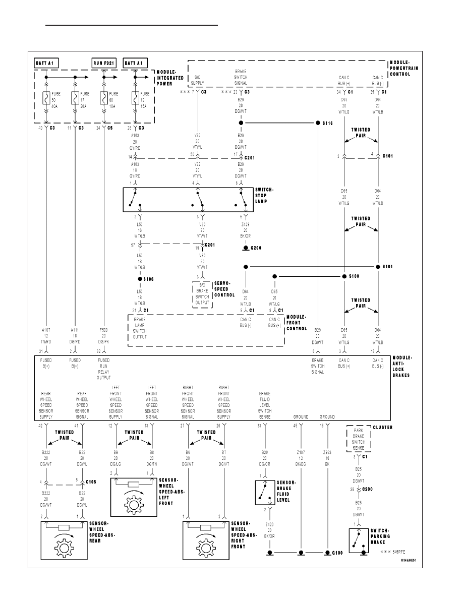
For a complete wiring diagram Refer to Section 8W.
Diagnostic Test
1.
LOST COMMUNICATION WITH FRONT CONTROL MODULE (FCM)
The Anti-lock Brake Module is reporting that network communication has been lost with the Front Control Module
(FCM).
View repair.
Repair
Refer to 8 — ELECTRICAL/ELECTRONIC CONTROL MODULES — DIAGNOSIS AND TESTING for
diagnostic procedures and for further possible causes.
5 - 222
BRAKES - ABS ELECTRICAL DIAGNOSTICS
ND
U1003–ESP CAN C BUS PERFORMANCE (340)
ND
BRAKES - ABS ELECTRICAL DIAGNOSTICS
5 - 223

U1003–ESP CAN C BUS PERFORMANCE (340) (CONTINUED)
For a complete wiring diagram Refer to Section 8W.
•
When Monitored:
Continuously.
•
Set Condition:
One of the CAN messages that is assigned to the basic CAN channel was missed by the CAN driver. This
means that the whole system was very slow in responding to the CAN interrupts.
Possible Causes
INTERMITTENT ESP CAN C BUS PERFORMANCE DTC
CAN C BUS DTCs SET IN FRONT CONTROL MODULE
(D65) CAN C BUS (+) CIRCUIT OPEN
(D64) CAN C BUS (-) CIRCUIT OPEN
ANTI-LOCK BRAKE MODULE
Diagnostic Test
1.
DTC IS ACTIVE
Ignition on, engine not running.
With the scan tool, clear DTCs in the Anti-lock Brake Module.
Cycle the ignition from off to on at least 5 times, leaving the ignition on for a minimum of 90 seconds per cycle.
With the scan tool, select View DTCs in the Anti-lock Brake Module.
Does the DTC reset and/or remain active?
Yes
>> Go to 2
No
>> Go to 6
2.
CAN C BUS DTCs SET IN FRONT CONTROL MODULE
With the scan tool, select View DTCs in the Front Control Module (FCM).
Are there any active CAN C Bus DTCs?
Yes
>> Refer to 8 — ELECTRICAL/ELECTRONIC CONTROL MODULES — DIAGNOSIS AND TESTING for
diagnostic procedures and for further possible causes.
No
>> Go to 3
5 - 224
BRAKES - ABS ELECTRICAL DIAGNOSTICS
ND

U1003–ESP CAN C BUS PERFORMANCE (340) (CONTINUED)
3.
(D65) CAN C BUS (+) CIRCUIT OPEN
Turn the ignition off.
Disconnect the Anti-lock Brake Module harness connector.
Disconnect the Front Control Module C1 harness connector.
Measure the resistance of the (D65) CAN C Bus (+) circuit between
the Anti-lock Brake Module harness connector and the Front Control
Module C1 harness connector.
Is the resistance above 2.0 ohms?
Yes
>> Repair the (D65) CAN C Bus (+) circuit for an open.
Perform ABS VERIFICATION TEST - VER 1. (Refer to 5 -
BRAKES/ELECTRICAL - DIAGNOSIS AND TESTING)
No
>> Go to 4
4.
(D64) CAN C BUS (-) CIRCUIT OPEN
Measure the resistance of the (D64) CAN C Bus (-) circuit between
the Anti-lock Brake Module harness connector and the Front Control
Module C1 harness connector.
Is the resistance above 2.0 ohms?
Yes
>> Repair the (D64) CAN C Bus (-) circuit for an open.
Perform ABS VERIFICATION TEST - VER 1. (Refer to 5 -
BRAKES/ELECTRICAL - DIAGNOSIS AND TESTING)
No
>> Go to 5
ND
BRAKES - ABS ELECTRICAL DIAGNOSTICS
5 - 225
Нет комментариевНе стесняйтесь поделиться с нами вашим ценным мнением.
Текст