Dodge Dakota (ND). Manual — part 1038
P0868-LINE PRESSURE LOW (CONTINUED)
8.
(F856) 5-VOLT SUPPLY CIRCUIT OPEN
Turn the ignition off to the lock position.
Disconnect the PCM C1 harness connector and connect Miller tool
#8815.
CAUTION: Do not probe the PCM harness connectors. Probing
the PCM harness connectors will damage the PCM terminals
resulting in poor terminal to pin connection. Install Miller tool
#8815 to perform diagnosis.
Measure the resistance of the (F856) 5-volt Supply circuit from the
Line Pressure Sensor harness connector to the appropriate terminal of
Miller tool #8815.
Is the resistance above 5.0 ohms?
Yes
>> Repair the (F856) 5-volt Supply circuit for an open.
Perform 45RFE/545RFE TRANSMISSION VERIFICATION
TEST - VER 1.
No
>> Go To 9
9.
(F856) 5-VOLT SUPPLY CIRCUIT SHORT TO GROUND
Measure the resistance between ground and the (F856) 5-volt Supply
circuit.
Is the resistance below 5.0 ohms?
Yes
>> Repair the (F856) 5-volt Supply circuit for a short to
ground.
Perform 45RFE/545RFE TRANSMISSION VERIFICATION
TEST - VER 1.
No
>> Go To 10
21 - 544
AUTOMATIC TRANSMISSION 545RFE - ELECTRICAL DIAGNOSTICS
ND
P0868-LINE PRESSURE LOW (CONTINUED)
10.
(T140) PRESSURE CONTROL SOLENOID CONTROL CIRCUIT SHORT TO ANOTHER CIRCUIT
Turn the ignition off to the lock position.
Disconnect the Transmission Solenoid/TRS Assembly harness connec-
tor.
Disconnect all PCM harness connectors.
Measure the resistance between the (T140) Pressure Control Solenoid
Control circuit and all other circuits in the Transmission Solenoid/TRS
Assembly harness connector.
Is the resistance below 5.0 ohms between the (T140) Pressure
Control Solenoid Control circuit and any other circuit(s) in the
Transmission Solenoid/TRS Assembly harness connector?
Yes
>> Repair the (T140) Pressure Control Solenoid Control cir-
cuit for a short to another circuit(s).
Perform 45RFE/545RFE TRANSMISSION VERIFICATION
TEST - VER 1.
No
>> Using the schematics as a guide, check the Powertrain
Control Module (PCM) terminals for corrosion, damage, or terminal push out. Pay particular attention to
all power and ground circuits. If no problems are found, replace the PCM per the Service Information.
With the scan tool, perform QUICK LEARN.
Perform 45RFE/545RFE TRANSMISSION VERIFICATION TEST - VER 1.
11.
INTERMITTENT WIRING AND CONNECTORS
The conditions necessary to set this DTC are not present at this time.
Using the schematics as a guide, inspect the wiring and connectors specific to this circuit.
Wiggle the wires while checking for shorted and open circuits.
With the scan tool, check the EATX DTC EVENT DATA to help identify the conditions in which the DTC was set.
Where there any problems found?
Yes
>> Repair as necessary.
Perform 45RFE/545RFE TRANSMISSION VERIFICATION TEST - VER 1.
No
>> Test Complete.
ND
AUTOMATIC TRANSMISSION 545RFE - ELECTRICAL DIAGNOSTICS
21 - 545
P0869-LINE PRESSURE HIGH
21 - 546
AUTOMATIC TRANSMISSION 545RFE - ELECTRICAL DIAGNOSTICS
ND
P0869-LINE PRESSURE HIGH (CONTINUED)
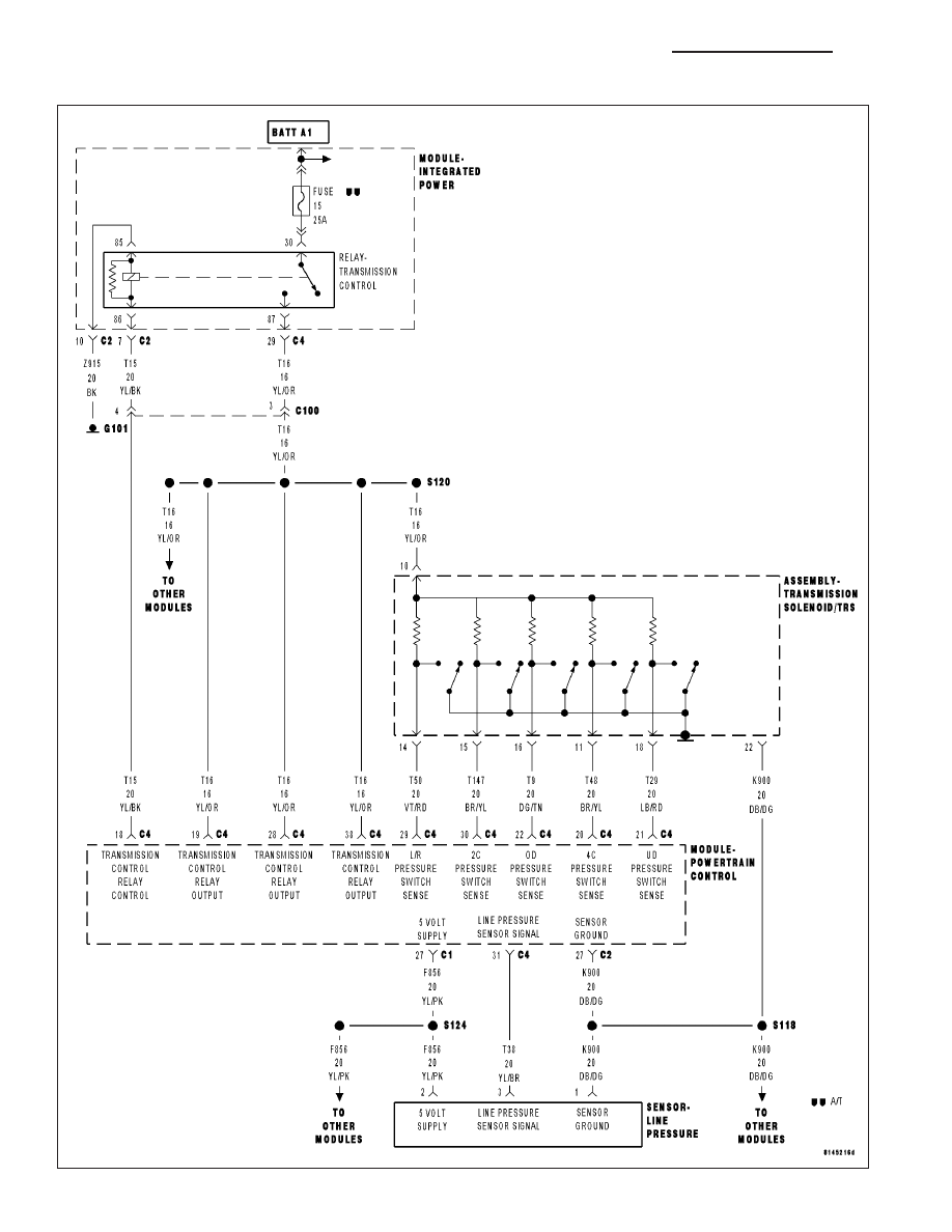
For the Transmission circuit diagram (Refer to 21 - TRANSMISSION/TRANSAXLE/AUTOMATIC - 45RFE/545RFE -
SCHEMATICS AND DIAGRAMS).
For a complete wiring diagram Refer to Section 8W
•
When Monitored:
Continuously while driving in a forward gear.
•
Set Condition:
The PCM continuously monitors Actual Line Pressure. If the Actual Line Pressure reading is greater than the
highest Desired Line Pressure ever used in the current gear, while the Pressure Control Solenoid duty cycle is
at or near its maximum value (which should result in minimum line pressure), the DTC will set.
Possible Causes
(F856) 5-VOLT SUPPLY CIRCUIT OPEN
LINE PRESSURE SENSOR CONNECTION
(T140) PRESSURE CONTROL SOLENOID CONTROL CIRCUIT OPEN
(F856) 5-VOLT SUPPLY CIRCUIT SHORT TO GROUND
(T140) PRESSURE CONTROL SOLENOID CONTROL CIRCUIT SHORT TO GROUND
ITRANSMISSION CONTROL RELAY OUTPUT CIRCUIT
LINE PRESSURE SENSOR
STUCK OR STICKING MAIN REGULATOR VALVE
POWERTRAIN CONTROL MODULE
Always perform the Pre-Diagnostic Troubleshooting procedure before proceeding. (Refer to 21 - TRANSMIS-
SION/TRANSAXLE/AUTOMATIC - 45RFE/545RFE - DIAGNOSIS AND TESTING).
Theory of Operation
Line pressure is measured by the Line Pressure Sensor (LPS) and regulation is achieved by changing the duty
cycle of the Pressure Control Solenoid (PCS) controlled by the Transmission Control System. (5% duty cycle =
solenoid off = max line pressure, 62% duty cycle = solenoid on = min line pressure). The Transmission Control
System calculates the desired line pressure based on inputs from both the engine and transmission.
The Transmission Control System calculates torque input to the transmission and uses it as the primary input to the
desired line pressure calculation. This is called Torque Based Line Pressure. In addition, the line pressure is set to
a preset level 827 or 931kPa (120 or 135 PSI) during shifts and in Park and Neutral to ensure consistent shift
quality. The desired line pressure is continuously being compared to the actual line pressure. If the actual line pres-
sure is consistently higher than the highest desired line pressure ever used in the current gear, the line pressure
high DTC P0869 will set.
Diagnostic Test
1.
CHECK FOR RELATED DTC’S
With the scan tool, check for other Transmission DTC’s
Is the DTC P0932 or P0888 present also?
Yes
>> Refer to the Transmission category and perform the appropriate symptom.
Perform 45RFE/545RFE TRANSMISSION VERIFICATION TEST - VER 1.
No
>> Go To 2
ND
AUTOMATIC TRANSMISSION 545RFE - ELECTRICAL DIAGNOSTICS
21 - 547
Нет комментариевНе стесняйтесь поделиться с нами вашим ценным мнением.
Текст