Dodge Dakota (ND). Manual — part 711
P0340-CAMSHAFT POSITION SENSOR CIRCUIT (CONTINUED)
4.
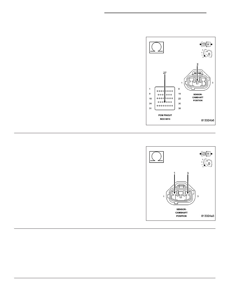
(K900) SENSOR GROUND CIRCUIT OPEN
Turn the ignition off.
Disconnect the C2 PCM harness connector.
CAUTION: Do not probe the PCM harness connectors. Probing
the PCM harness connectors will damage the PCM terminals
resulting in poor terminal to pin connection. Install Miller Special
Tool #8815 to perform diagnosis.
Measure the resistance of the (K900) Sensor ground circuit from the
CMP Sensor harness connector to the appropriate terminal of special
tool #8815.
Is the resistance below 5.0 ohms?
Yes
>> Go To 5
No
>> Repair the open in the (K900) Sensor ground circuit.
Perform POWERTRAIN VERIFICATION TEST. (Refer to 9
- ENGINE - STANDARD PROCEDURE)
5.
(K44) CMP SIGNAL SHORTED TO THE (F856) 5-VOLT SUPPLY CIRCUIT
Disconnect the C1 PCM harness connector.
Measure the resistance between the (K44) CMP Signal circuit and the
(F856) 5-volt Supply circuit in the CMP Sensor harness connector.
Is the resistance below 5.0 ohms?
Yes
>> Repair the short between the (K44) CMP Signal circuit and
the (F856) 5-volt Supply circuit.
Perform POWERTRAIN VERIFICATION TEST. (Refer to 9
- ENGINE - STANDARD PROCEDURE)
No
>> Go To 6
6.
CAMSHAFT POSITION SENSOR
NOTE: Inspect the Camshaft sprocket for damage per the Service Information. If a problem is found repair
as necessary.
If there are no possible causes remaining, view repair.
Repair
Replace the Camshaft Position Sensor.
Perform POWERTRAIN VERIFICATION TEST. (Refer to 9 - ENGINE - STANDARD PROCEDURE)
9 - 382
ENGINE ELECTRICAL DIAGNOSTICS
ND
P0340-CAMSHAFT POSITION SENSOR CIRCUIT (CONTINUED)
7.
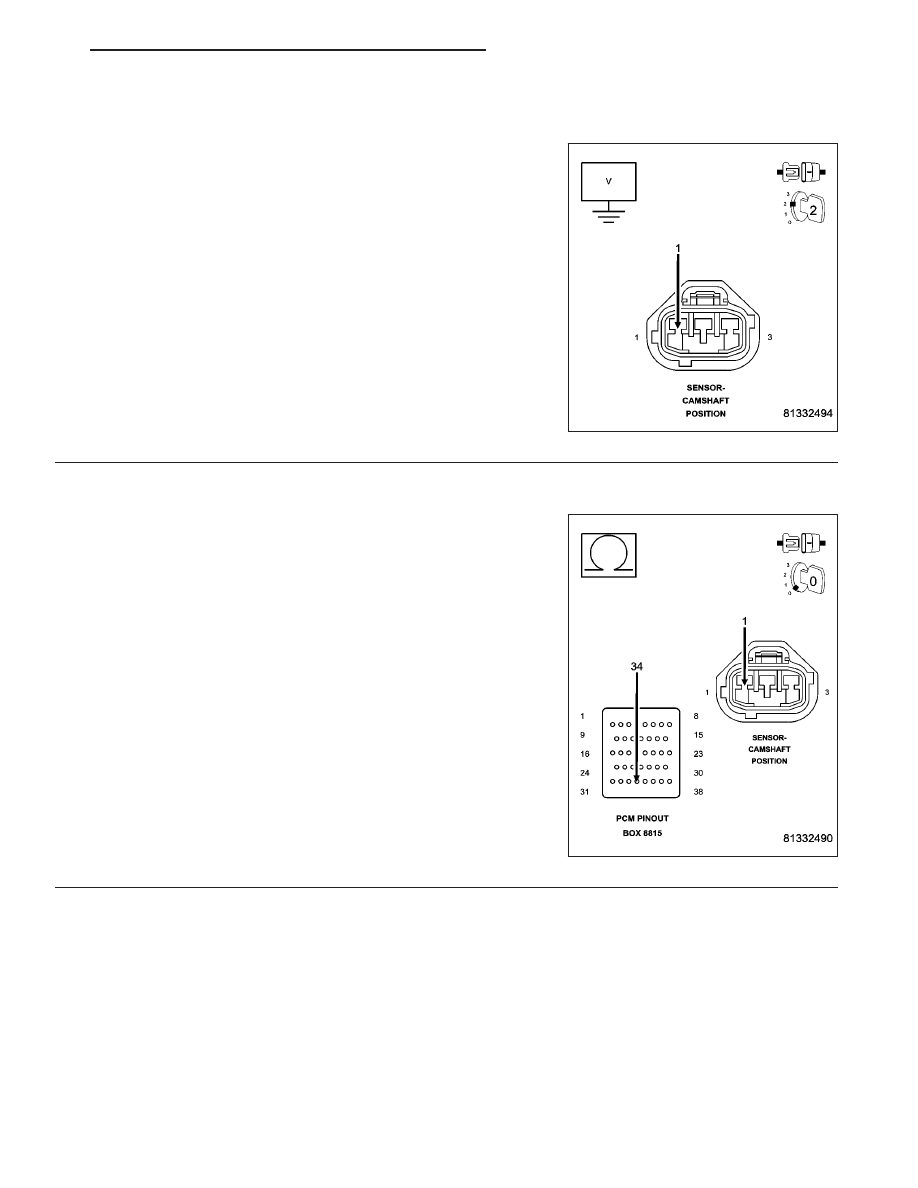
(K44) CMP SIGNAL CIRCUIT SHORTED TO BATTERY VOLTAGE
Turn the ignition off.
Disconnect the C1 and C2 PCM harness connectors.
Ignition on, engine not running.
Measure the voltage on the (K44) CMP Signal circuit in the CMP Sen-
sor harness connector.
Is the voltage above 0 volts?
Yes
>> Repair the short to battery voltage in the (K44) CMP Sig-
nal circuit.
Perform POWERTRAIN VERIFICATION TEST. (Refer to 9
- ENGINE - STANDARD PROCEDURE)
No
>> Go To 8
8.
(K44) CMP SIGNAL CIRCUIT OPEN
Turn the ignition off.
CAUTION: Do not probe the PCM harness connectors. Probing
the PCM harness connectors will damage the PCM terminals
resulting in poor terminal to pin connection. Install Miller Special
Tool #8815 to perform diagnosis.
Measure the resistance of the (K44) CMP Signal circuit from the CMP
Sensor harness connector to the appropriate terminal of special tool
#8815.
Is the resistance below 5.0 ohms?
Yes
>> Go To 9
No
>> Repair the open in the (K44) CMP Signal circuit.
Perform POWERTRAIN VERIFICATION TEST. (Refer to 9
- ENGINE - STANDARD PROCEDURE)
ND
ENGINE ELECTRICAL DIAGNOSTICS
9 - 383
P0340-CAMSHAFT POSITION SENSOR CIRCUIT (CONTINUED)
9.
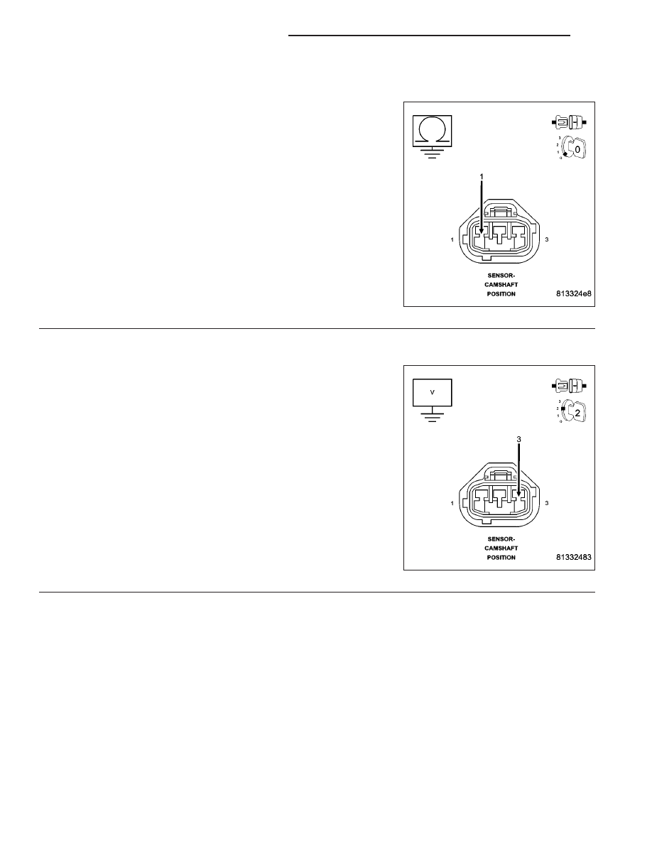
(K44) CMP SIGNAL CIRCUIT SHORTED TO GROUND
Measure the resistance between ground and the (K44) CMP Signal
circuit in the CMP Sensor harness connector.
Is the resistance below 100 ohms?
Yes
>> Repair the short to ground in the (K44) CMP Signal circuit
Perform POWERTRAIN VERIFICATION TEST. (Refer to 9
- ENGINE - STANDARD PROCEDURE)
No
>> Go To 10
10.
(F856) 5-VOLT SUPPLY CIRCUIT SHORTED TO BATTERY VOLTAGE
Ignition on, engine not running.
Measure the voltage on the (F856) 5-volt Supply circuit in the CMP
Sensor harness connector.
Is the voltage above 0 volts?
Yes
>> Repair the short to battery voltage in the (F856) 5-volt
Supply circuit.
Perform POWERTRAIN VERIFICATION TEST. (Refer to 9
- ENGINE - STANDARD PROCEDURE)
No
>> Go To 11
9 - 384
ENGINE ELECTRICAL DIAGNOSTICS
ND
P0340-CAMSHAFT POSITION SENSOR CIRCUIT (CONTINUED)
11.
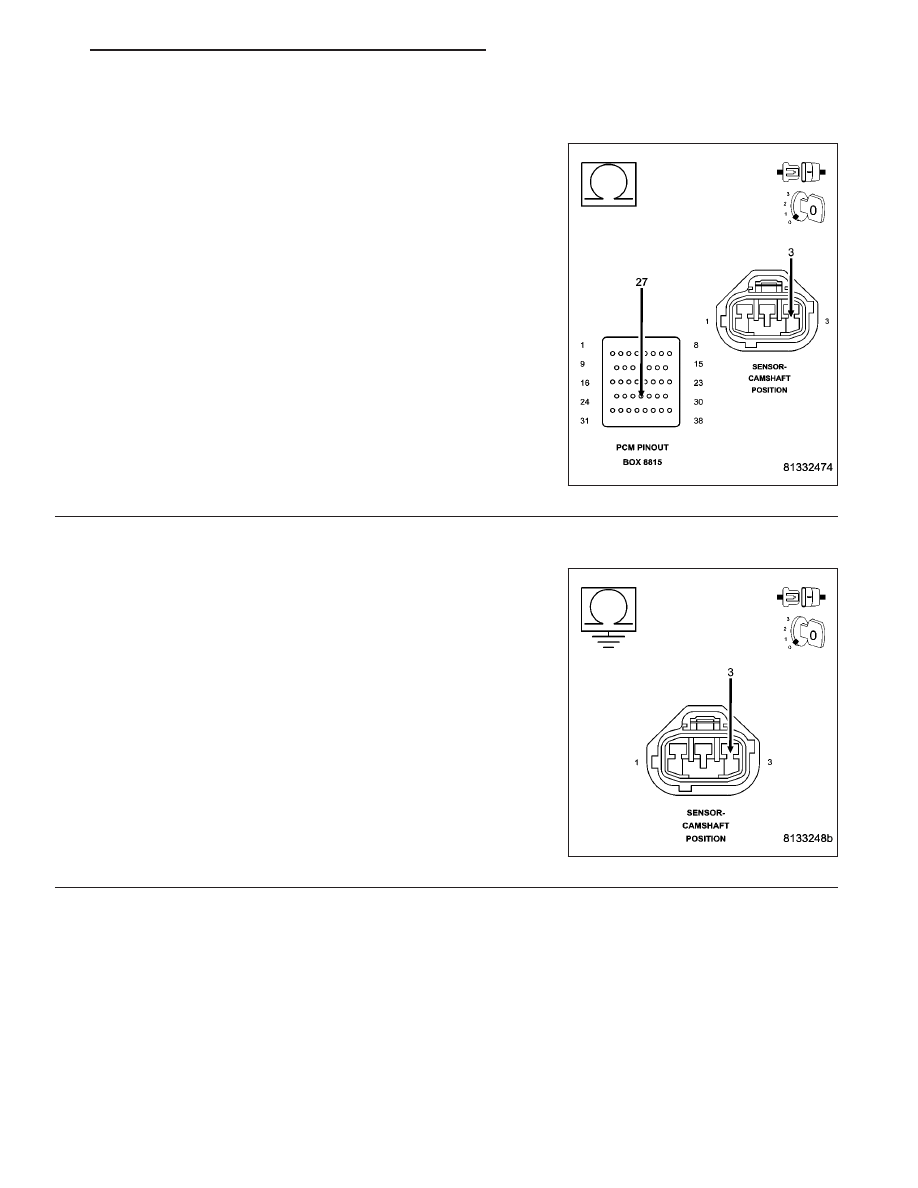
(F856) 5-VOLT SUPPLY CIRCUIT OPEN
Turn the ignition off.
CAUTION: Do not probe the PCM harness connectors. Probing
the PCM harness connectors will damage the PCM terminals
resulting in poor terminal to pin connection. Install Miller Special
Tool #8815 to perform diagnosis.
Measure the resistance of the (F856) 5-volt Supply circuit between the
CMP Sensor harness connector to the appropriate terminal of special
tool #8815.
Is the resistance below 5.0 ohms?
Yes
>> Go To 12
No
>> Repair the open in the (F856) 5-volt Supply circuit.
Perform POWERTRAIN VERIFICATION TEST. (Refer to 9
- ENGINE - STANDARD PROCEDURE)
12.
(F856) 5-VOLT SUPPLY CIRCUIT SHORTED TO GROUND
Measure the resistance between ground and the (F856) 5-volt Supply
circuit in the CMP Sensor harness connector.
Is the resistance below 100 ohms?
Yes
>> Repair the short to ground in the (F856) 5-volt Supply cir-
cuit.
Perform POWERTRAIN VERIFICATION TEST. (Refer to 9
- ENGINE - STANDARD PROCEDURE)
No
>> Go To 13
ND
ENGINE ELECTRICAL DIAGNOSTICS
9 - 385
Нет комментариевНе стесняйтесь поделиться с нами вашим ценным мнением.
Текст