Dodge Dakota (ND). Manual — part 710
P0339-CRANKSHAFT POSITION SENSOR INTERMITTENT (CONTINUED)
12.
PCM
NOTE: Before continuing, check the PCM harness connector terminals for corrosion, damage, or terminal
push out. Repair as necessary.
Using the schematics as a guide, inspect the wire harness and connectors. Pay particular attention to all Power and
Ground circuits.
Were there any problems found?
Yes
>> Repair as necessary.
Perform POWERTRAIN VERIFICATION TEST. (Refer to 9 - ENGINE - STANDARD PROCEDURE)
No
>> Replace and program the Powertrain Control Module per Service Information.
Perform POWERTRAIN VERIFICATION TEST. (Refer to 9 - ENGINE - STANDARD PROCEDURE)
9 - 378
ENGINE ELECTRICAL DIAGNOSTICS
ND
P0340-CAMSHAFT POSITION SENSOR CIRCUIT
ND
ENGINE ELECTRICAL DIAGNOSTICS
9 - 379
P0340-CAMSHAFT POSITION SENSOR CIRCUIT (CONTINUED)
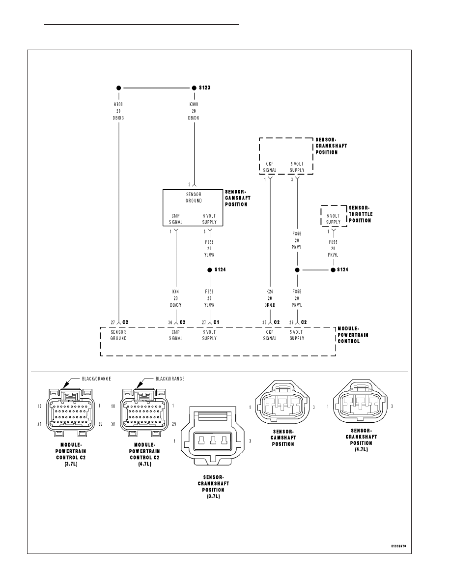
For the Engine circuit diagram (Refer to 9 - ENGINE - SCHEMATICS AND DIAGRAMS).
For a complete wiring diagram Refer to Section 8W.
•
When Monitored:
During engine cranking and with the engine running. Battery voltage greater than 10 volts.
•
Set Condition:
At least 5 seconds or 2.5 engine revolutions have elapsed with crankshaft position sensor signals present but
no camshaft position sensor signal. One Trip Fault. Three good trips to turn off the MIL.
Possible Causes
(F856) 5-VOLT SUPPLY CIRCUIT SHORTED TO BATTERY VOLTAGE
(F856) 5-VOLT SUPPLY CIRCUIT OPEN
(F856) 5-VOLT SUPPLY CIRCUIT SHORTED TO GROUND
(K44) CMP SIGNAL CIRCUIT SHORTED TO BATTERY VOLTAGE
(K44) CMP SIGNAL CIRCUIT OPEN
(K44) CMP SIGNAL CIRCUIT SHORTED GROUND
(K44) CMP SIGNAL SHORTED TO THE (F856) 5-VOLT SUPPLY CIRCUIT
(K900) SENSOR GROUND CIRCUIT OPEN
CAMSHAFT POSITION SENSOR
CRANKSHAFT POSITION SENSOR
PCM
Always perform the Pre-Diagnostic Troubleshooting procedure before proceeding. (Refer to 9 - ENGINE -
DIAGNOSIS AND TESTING).
Diagnostic Test
1.
ACTIVE DTC
Crank the engine.
Ignition on, engine not running.
With a scan tool read the DTCs.
Is the DTC active at this time?
Yes
>> Go To 2
No
>> Go To 14
9 - 380
ENGINE ELECTRICAL DIAGNOSTICS
ND
P0340-CAMSHAFT POSITION SENSOR CIRCUIT (CONTINUED)
2.
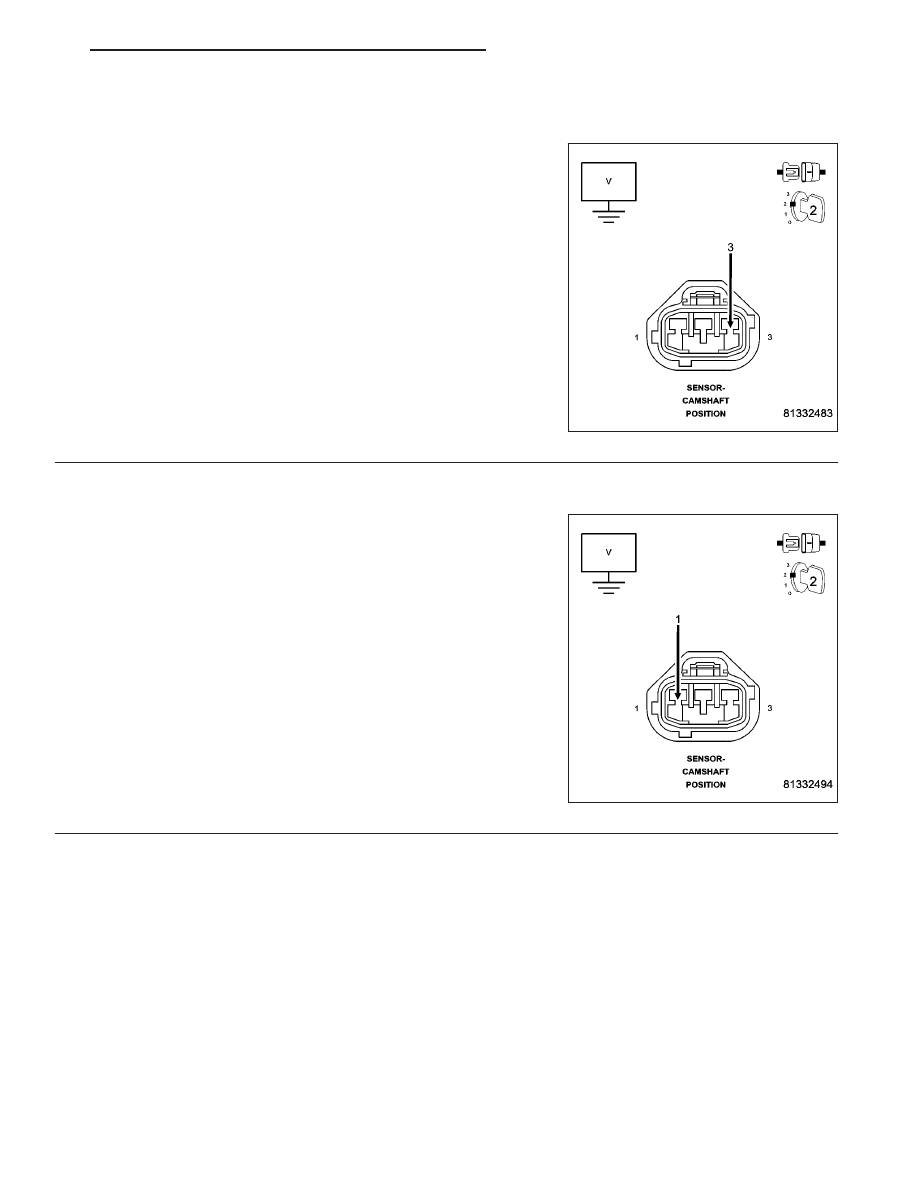
(F856) 5-VOLT SUPPLY CIRCUIT
Turn the ignition off.
Disconnect the CMP Sensor harness connector.
Ignition on, engine not running.
Measure the voltage on the (F856) 5-volt Supply circuit in the CMP
Sensor harness connector.
Is the voltage between 4.5 and 5.2 volts?
Yes
>> Go To 3
No
>> Go To 10
3.
(K44) CMP SIGNAL CIRCUIT
Measure the voltage on the (K44) CMP Signal circuit in the CMP Sen-
sor harness connector.
Is the voltage between 4.5 and 5.0 volts?
Yes
>> Go To 4
No
>> Go To 7
ND
ENGINE ELECTRICAL DIAGNOSTICS
9 - 381
Нет комментариевНе стесняйтесь поделиться с нами вашим ценным мнением.
Текст