Dodge Dakota (ND). Manual — part 267
B1615-PANEL ILLUMINATION CONTROL CIRCUIT OPEN (CONTINUED)
2.
CHECK CONDITION OF THE WIRING AND CONNECTORS ASSOCIATED WITH THE PANEL
ILLUMINATION OUTPUT CIRCUITS
Turn the ignition off.
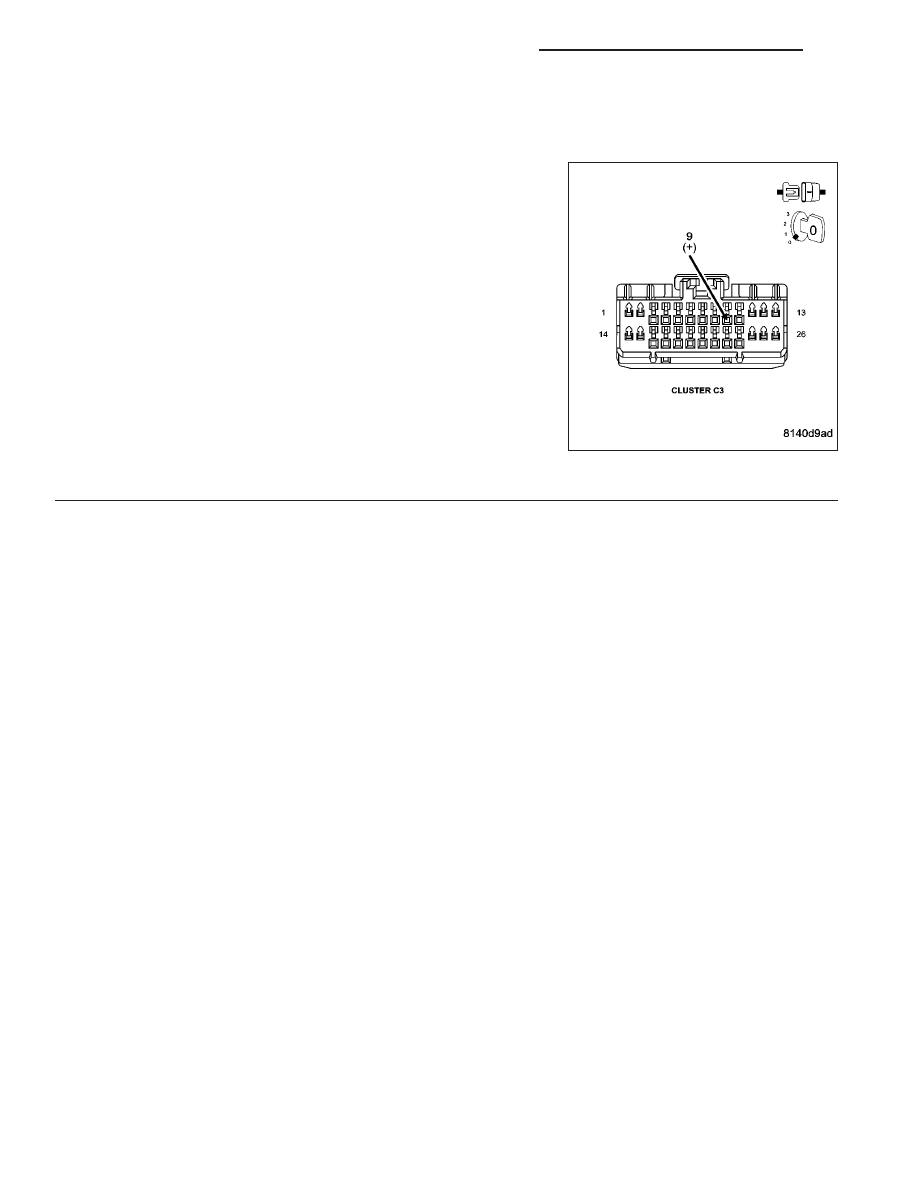
Disconnect the Instrument Cluster C3 harness connector and inspect
the connector and associated wiring for the Panel Illumination System.
Using a fused jumper wire, probe cavity 9 of the Instrument Cluster C3
connector.
Did the illumination of the Headlamp Switch illuminate?
Yes
>> Replace the Instrument Cluster in accordance with the
Service Information.
Perform the BODY VERIFICATION TEST-VER 1. (Refer to
8 - ELECTRICAL/ELECTRONIC CONTROL MODULES/
FRONT CONTROL MODULE - DIAGNOSIS AND TEST-
ING)
No
>> Repair the faulty wire(s)/connector(s).
Perform the BODY VERIFICATION TEST-VER 1. (Refer to
8 - ELECTRICAL/ELECTRONIC CONTROL MODULES/
FRONT CONTROL MODULE - DIAGNOSIS AND TESTING)
8J - 10
INSTRUMENT CLUSTER - ELECTRICAL DIAGNOSTICS
ND
B2107–IGNITION SWITCH SENSE INPUT CIRCUIT/PERFORMANCE
ND
INSTRUMENT CLUSTER - ELECTRICAL DIAGNOSTICS
8J - 11

B2107–IGNITION SWITCH SENSE INPUT CIRCUIT/PERFORMANCE (CONTINUED)
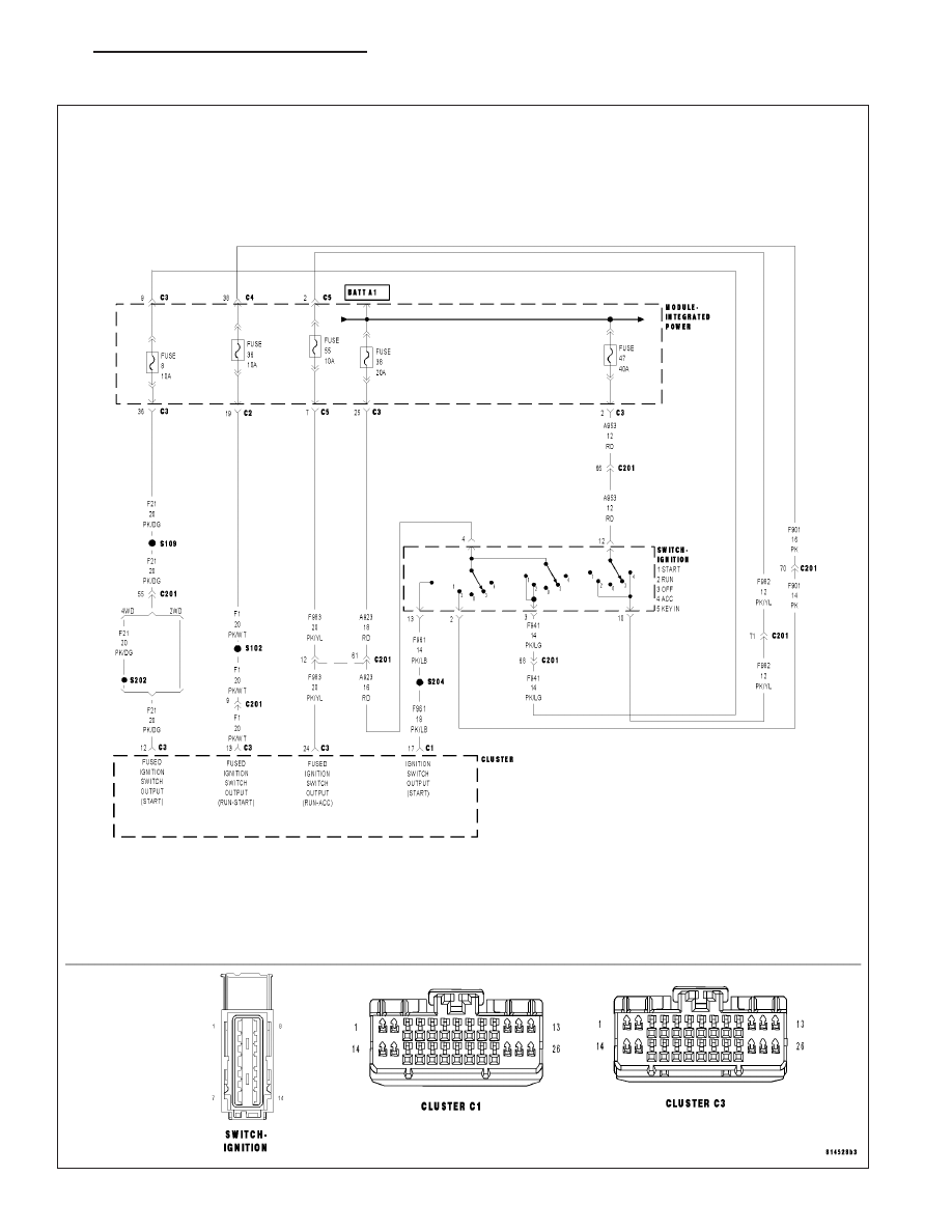
For the Instrument Cluster circuit diagram (Refer to 8 - ELECTRICAL/INSTRUMENT CLUSTER - SCHEMATICS
AND DIAGRAMS).
For a complete wiring diagram Refer to Section 8W.
•
When Monitored:
With the ignition on.
•
Set Condition:
The Cluster detects an Ignition Switch performance fault.
Possible Causes
OPEN IGNITION SWITCH OUTPUT FUSE(S)
(F21) IGNITION SWITCH OUTPUT (OFF/RUN/START) CIRCUIT OPEN OR SHORTED TO GROUND
(F1) IGNITION SWITCH OUTPUT (RUN/START) CIRCUIT OPEN OR SHORTED TO GROUND
(F961) IGNITION SWITCH OUTPUT (RUN) CIRCUIT OPEN OR SHORTED TO GROUND
(F983) IGNITION SWITCH OUTPUT (RUN/ACC) CIRCUIT OPEN OR SHORTED TO GROUND
(A953) IGNITION (RUN/ACC) CIRCUIT OPEN OR SHORTED TO GROUND
IGNITION SWITCH
INSTRUMENT CLUSTER
Diagnostic Test
1.
TEST FOR AN INTERMITTENT CONDITION
NOTE: Troubleshoot any Ignition, Battery, or Cluster DTCs before proceeding.
Turn the ignition on.
Using the scan tool, record and erase DTCs.
Turn the ignition off, wait 10 seconds then turn the ignition on.
Using the scan tool, read DTCs.
Does the scan tool display: B2107–IGNITION SWITCH SENSE INPUT CIRCUIT/PERFORMANCE?
Yes
>> Go To 2
No
>> The condition that caused this code to set is not present at this time. Using the wiring diagram as a
guide, inspect the wiring and connectors for an intermittent condition. Operate the system several times
and recheck for active DTCs.
Perform the BODY VERIFICATION TEST-VER 1. (Refer to 8 - ELECTRICAL/ELECTRONIC CONTROL
MODULES/FRONT CONTROL MODULE - DIAGNOSIS AND TESTING)
8J - 12
INSTRUMENT CLUSTER - ELECTRICAL DIAGNOSTICS
ND
B2107–IGNITION SWITCH SENSE INPUT CIRCUIT/PERFORMANCE (CONTINUED)
2.
CHECK FOR OPEN IGNITION SWITCH OUTPUT FUSES
Turn the ignition off.
Using the wiring/circuit diagrams, check the following fuses for an open:
•
IPM fuse #8
•
IPM fuse #36
•
IPM fuse #38
•
IPM fuse #47
•
IPM fuse #55
Are any of the fuses open?
Yes
>> Go To 3
No
>> Go To 4
3.
CHECK FOR OPEN IGNITION SWITCH OUTPUT FUSES
Replace the open fuse(s).
Cycle the ignition through ALL positions.
Turn the ignition off.
Check each fuse that was replaced for an open.
NOTE: Perform the diagnostic procedure for each fuse that is open before making any repairs. Doing so will
identify all possible conditions causing this DTC to set.
Was any replaced fuse open? (Select from the following)
IPM fuse #55
Go To 9
IPM fuse #8
Go To 10
IPM fuse #36
Go To 11
IPM fuse #38
Go To 12
IPM fuse #47
Go To 15
No fuses open
The condition that caused the fuse(s) to open is not present at this time. Using the wiring diagram as a
guide, inspect the wiring and connectors for an intermittent condition. Operate the system several times
and recheck for active DTCs.
Perform the BODY VERIFICATION TEST-VER 1. (Refer to 8 - ELECTRICAL/ELECTRONIC CONTROL
MODULES/FRONT CONTROL MODULE - DIAGNOSIS AND TESTING)
ND
INSTRUMENT CLUSTER - ELECTRICAL DIAGNOSTICS
8J - 13
Нет комментариевНе стесняйтесь поделиться с нами вашим ценным мнением.
Текст