Dodge Dakota (ND). Manual — part 266
B1613-PANEL ILLUMINATION CONTROL CIRCUIT LOW (CONTINUED)
3.
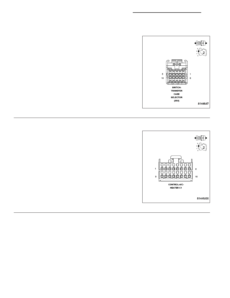
CHECK THE TRANSFER CASE SELECTOR SWITCH FOR AN INTERNAL SHORT
Reconnect the Headlamp Switch harness connector.
With the scan tool, erase Instrument Cluster DTCs.
Turn the ignition off.
Disconnect the Transfer Case Selector Switch harness connector.
Turn the ignition on.
With the scan tool, read DTCs.
Does the scan tool display B1613-PANEL ILLUMINATION CON-
TROL CIRCUIT LOW?
Yes
>> Go To 4
No
>> Replace the Transfer Case Selector Switch in accordance
with the service information.
Perform the BODY VERIFICATION TEST-VER 1. (Refer to
8 - ELECTRICAL/ELECTRONIC CONTROL MODULES/
FRONT CONTROL MODULE - DIAGNOSIS AND TEST-
ING)
4.
CHECK THE A/C HEATER CONTROL FOR AN INTERNAL SHORT
Reconnect the Heated Seat Passenger Switch harness connector.
With the scan tool, erase Instrument Cluster DTCs.
Turn the ignition off.
Disconnect the A/C Heater Control C1 harness connector.
Turn the ignition on.
With the scan tool, read DTCs.
Does the scan tool display B1613-PANEL ILLUMINATION CON-
TROL CIRCUIT LOW?
Yes
>> Go To 5
No
>> Replace the A/C Heater Control in accordance with the
service information.
Perform the BODY VERIFICATION TEST-VER 1. (Refer to
8 - ELECTRICAL/ELECTRONIC CONTROL MODULES/
FRONT CONTROL MODULE - DIAGNOSIS AND TEST-
ING)
8J - 6
INSTRUMENT CLUSTER - ELECTRICAL DIAGNOSTICS
ND
B1613-PANEL ILLUMINATION CONTROL CIRCUIT LOW (CONTINUED)
5.
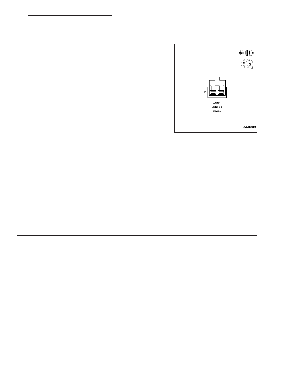
CHECK THE CENTER BEZEL LAMP FOR AN INTERNAL SHORT
Reconnect the Rear A/C Heater Control harness connector.
With the scan tool, erase Instrument Cluster DTCs.
Turn the ignition off.
Disconnect the Center Bezel Lamp harness connector.
Turn the ignition on.
With the scan tool, read DTCs.
Does the scan tool display B1613-PANEL ILLUMINATION CON-
TROL CIRCUIT LOW?
Yes
>> Go To 6
No
>> Replace the Center Bezel Lamp in accordance with the
service information.
Perform the BODY VERIFICATION TEST-VER 1. (Refer to
8 - ELECTRICAL/ELECTRONIC CONTROL MODULES/
FRONT CONTROL MODULE - DIAGNOSIS AND TEST-
ING)
6.
PANEL LAMPS DIMMING CIRCUIT SHORTED TO GROUND
Turn the ignition off.
Disconnect the Instrument Cluster C3 harness connector.
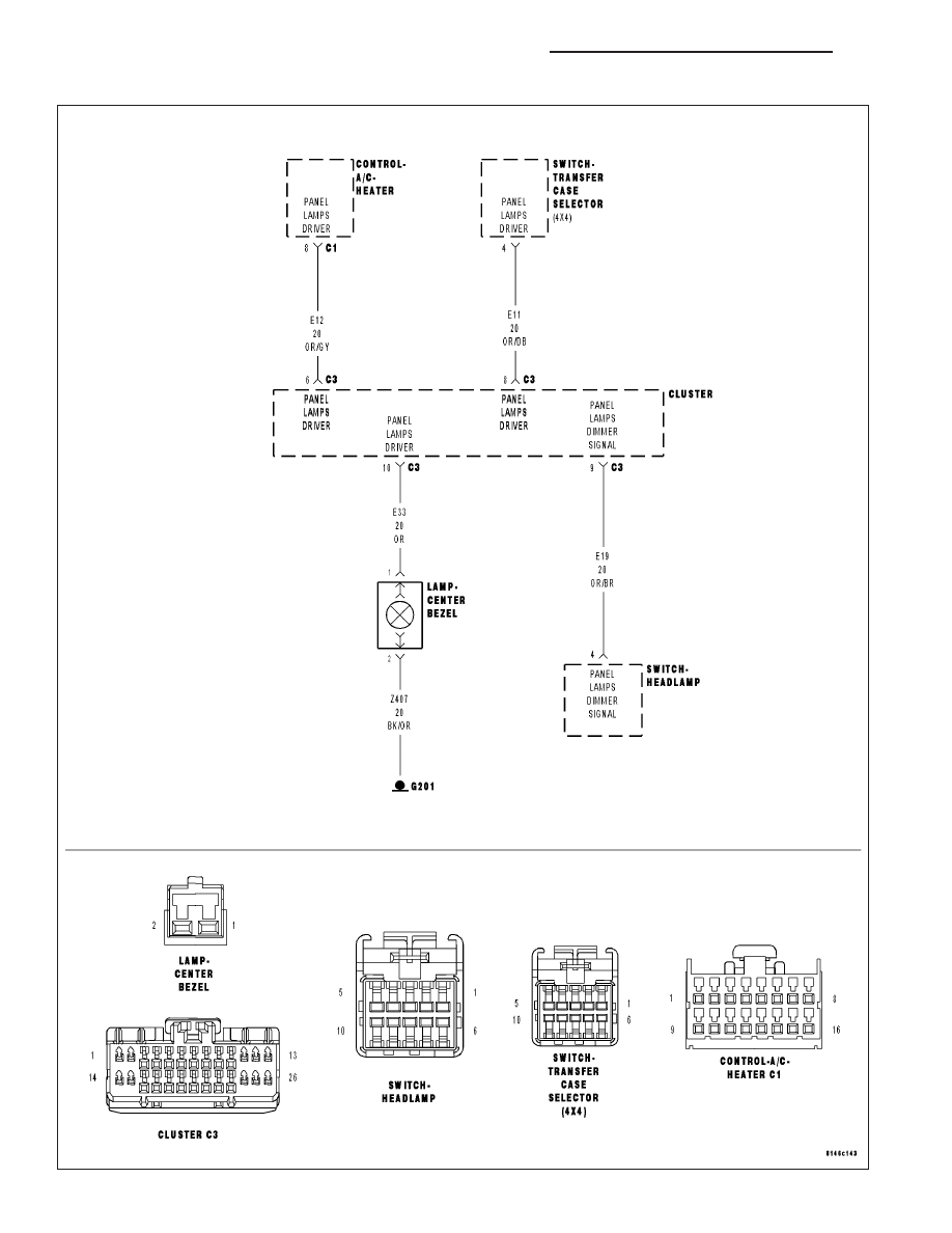
Using the wiring diagram as a guide, disconnect each dimmed component and measure the resistance of the Panel
Illumination Control Circuits from the Cluster C3 harness connector to ground.
Was there a short to ground condition found?
Yes
>> Repair the correct Panel Illumination Circuit for a short to ground.
Perform the BODY VERIFICATION TEST-VER 1. (Refer to 8 - ELECTRICAL/ELECTRONIC CONTROL
MODULES/FRONT CONTROL MODULE - DIAGNOSIS AND TESTING)
No
>> Replace the Instrument Cluster in accordance with the Service Information.
Perform the BODY VERIFICATION TEST-VER 1. (Refer to 8 - ELECTRICAL/ELECTRONIC CONTROL
MODULES/FRONT CONTROL MODULE - DIAGNOSIS AND TESTING)
ND
INSTRUMENT CLUSTER - ELECTRICAL DIAGNOSTICS
8J - 7
B1615-PANEL ILLUMINATION CONTROL CIRCUIT OPEN
8J - 8
INSTRUMENT CLUSTER - ELECTRICAL DIAGNOSTICS
ND

B1615-PANEL ILLUMINATION CONTROL CIRCUIT OPEN (CONTINUED)
For the Instrument Cluster circuit diagram (Refer to 8 - ELECTRICAL/INSTRUMENT CLUSTER - SCHEMATICS
AND DIAGRAMS).
For a complete wiring diagram Refer to Section 8W.
•
When Monitored:
With the ignition on.
•
Set Condition:
The Instrument Cluster detects an all open condition on the Panel Illumination Control circuits.
Possible Causes
ALL PANEL ILLUMINATON CIRCUITS OPEN
INSTRUMENT CLUSTER
Theory of Operation
The Panel Illumination Control Circuits share a common 12 volt driver from the Instrument Cluster. In order for this
DTC to be set, ALL Panel Illumination circuits must be open.
Diagnostic Test
1.
TEST FOR AN INTERMITTENT CONDITION
Turn the ignition on.
With the scan tool, record and erase DTCs.
Turn the ignition off, wait 10 seconds then turn the ignition on.
Turn the headlamps on.
With the scan tool, read DTCs.
Does the scan tool display: B1615-PANEL ILLUMINATION CONTROL CIRCUIT OPEN?
Yes
>> Go To 2
No
>> The condition that caused this code to set is not present at this time. Using the wiring diagram as a
guide, inspect the wiring and connectors for an intermittent condition. Operate the system several times
and recheck for active DTCs.
Perform the BODY VERIFICATION TEST-VER 1. (Refer to 8 - ELECTRICAL/ELECTRONIC CONTROL
MODULES/FRONT CONTROL MODULE - DIAGNOSIS AND TESTING)
ND
INSTRUMENT CLUSTER - ELECTRICAL DIAGNOSTICS
8J - 9
Нет комментариевНе стесняйтесь поделиться с нами вашим ценным мнением.
Текст